Workshop Dynamometer using BLDC motor

Thread Starter

ElNormo123

Joined Nov 17, 2021
24
Hi all

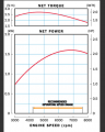
I am trying to make a brake dynamometer for a small 50cc engine (torque and power curves attached). The dyno must be capable of holding the torque of the engine at all speeds. I was thinking of using the following BLDC motor http://shop.dualsky.com/ga6000s-sin...-e-conversion-of-gasoline-airplane_p0253.html

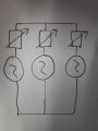
From what I can tell it can get up to the speeds required for the engine and provide a suitable torque. I am planning on electrically braking the motor by varying the resistance in the coils of all 3 phases as shown in the attached picture. To do this I will put some form of variable resistor in each wire coming from the motor and solder them all together. I am not very confident with motors so Im not sure if this will work. My theory is that as turning the BLDC with the engine will generate AC current, I should be able to regulate the resistance in each coil to regulate the current and hence braking torque.

I have a few questions about this.

1. When the engine is turning the motor will it generate sufficient current to create the necessary back torque? All the stats on the motors website give torque ratings with 48V across the motor, I assume I will not have 48V when im generating. My understanding of it is that I could use the RPM/V specification to calculate the volts is this true?

2. If the above is true, I have attached a file containing calculations using the max throttle specifications from the companys website (also attached as a screenshot), If these calcualtions are correct I should have more than twice the torque needed to hold the engine. I did the same calcualtions at various speeds and this remains true, I just want to check if the calcualtions would actually represent the true torque or at least close to it.

3. Last question is how to actually control the resistance. I have used PWM controlled Mosfets before with DC but as this will output an AC current I assume I cant still do this, does anyone know of a way to regulate the current affordably? If my calcualtions in Q2 are true I might be making a maximum current of 130A but as the resistors will only be in 1 coil each I assume I can have a resistor with a lower amp rating than this.

Any help would be greatly appreciated

Thanks

Moderators note : corrected link
 

Attachments

Last edited by a moderator:

shortbus

Joined Sep 30, 2009
10,045
Is there a reason you think you need to do it this way? Do you have multiples of the 50cc motor to test? I ask because there is a simpler way to do this, something that worked for a long, long time and is what a dynamometer is based on. It's called a "prony brake". Much simpler to do for a one off test, and even the most sophisticated dynos don't actually measure HP, it's calculated from the torque reading.

https://www.google.com/search?client=firefox-b-1-d&q=prony+brake

And how to make one at home - https://www.google.com/search?q=diy...GvCJIBBzAuMS4yLjGYAQCgAQHAAQE&sclient=gws-wiz
 

Thread Starter

ElNormo123

Joined Nov 17, 2021
24
Is there a reason you think you need to do it this way? Do you have multiples of the 50cc motor to test? I ask because there is a simpler way to do this, something that worked for a long, long time and is what a dynamometer is based on. It's called a "prony brake". Much simpler to do for a one off test, and even the most sophisticated dynos don't actually measure HP, it's calculated from the torque reading.

https://www.google.com/search?client=firefox-b-1-d&q=prony+brake

And how to make one at home - https://www.google.com/search?q=diy+prony+brake&client=firefox-b-1-d&sxsrf=AOaemvL7v3EsFaF5k-PJxBvzXKhQKAdy3A:1637161045572&ei=VRiVYYqPIompqtsP5rORSA&oq=DIY+prony+brake&gs_lcp=Cgdnd3Mtd2l6EAEYADIFCAAQgAQ6BAgAEA06BggAEA0QCjoGCC4QDRAKOgYIABAHEB46CAgAEAgQDRAeSgQIQRgAUABYoBFgpiVoAHACeACAAe8CiAGvCJIBBzAuMS4yLjGYAQCgAQHAAQE&sclient=gws-wiz
Ive read into Prony brakes but they lack the type of control Im looking for
 

Irving

Joined Jan 30, 2016
3,845
A DC motor will be much easier to control than a 3-phase BLDC; A 2.5hp treadmill motor would work, and they are rated for continuous operation. Also they often have a speed sensor (encoder) attached which makes torque calculations easier. Something like this: https://www.ebay.com/itm/274726248419


They are higher voltage than the BLDC so generate less current and are consequently easier to load up.

If you're set on a BLDC motor, consider rectifying the output with a 3-phase rectifier and then dealing with the DC from that; it'll be easier.
 
Last edited:

Thread Starter

ElNormo123

Joined Nov 17, 2021
24
A DC motor will be much easier to control than a 3-phase BLDC; A 2.5hp treadmill motor would work, and they are rated for continuous operation. Also they often have a speed sensor (encoder) attached which makes torque calculations easier. Something like this: https://www.ebay.com/itm/274726248419


They are higher voltage than the BLDC so generate less current and are consequently easier to load up.

If you're set on a BLDC motor, consider rectifying the output with a 3-phase rectifier and then dealing with the DC from that; it'll be easier.
The main reason I've gone for the brushless design is because of the voltage, our university requires many safety forms if we go above 48V. And most the brushed DC motors under 48V that were powerful enough draw alot of current that required expensive motorcontrollers.

The treadmill motor does seem like a good idea though, do you think it will be able to go above its rated speed? Our engine goes to a maximum speed of 8000rpm.
 

Irving

Joined Jan 30, 2016
3,845
They usually come with a pulley so you could belt drive it geared down and reduce volts too...

Yeah, university RiskNet project risk assessments, tell me about it...:rolleyes:
 

Sensacell

Joined Jun 19, 2012
3,432
In general, you would want to rectify the 3 phase output of the BLDC with a 3 phase diode bridge, then use a bank of well-cooled MOSFETS to dissipate the power in a controllable manner.

This contraption will not be very linear, nor will the torque be constant vs speed.
 

Irving

Joined Jan 30, 2016
3,845
In general, you would want to rectify the 3 phase output of the BLDC with a 3 phase diode bridge, then use a bank of well-cooled MOSFETS to dissipate the power in a controllable manner.

This contraption will not be very linear, nor will the torque be constant vs speed.
I've found treadmill and exercise bike motors to be pretty consistent as far as torque/speed/power is concerned. I've instrumented several treadmills/bikes for feedback/torque measurement for rehabilitation and training.

Agreed, as stated in my post #4, if a BLDC motor is used you need to work with the rectified DC output.

In either case there's some serious output power to be dissipated. I recently built a 1600W electronic load for a large battery testing rig (up to 40v at 40A,, 32v @ 50A). I used 8-off IXYS Linear2 MOSFETs on a big forced-air heatsink, though currently I'm running the numbers on a water-cooled solution as my office gets very hot and noisy with the air-cooled one. The Linear2 devices are designed for this purpose and are far better than any collection of general purpose MOSFETs as they have an extended safe operating area (SOA).
 

Thread Starter

ElNormo123

Joined Nov 17, 2021
24
I've found treadmill and exercise bike motors to be pretty consistent as far as torque/speed/power is concerned. I've instrumented several treadmills/bikes for feedback/torque measurement for rehabilitation and training.

Agreed, as stated in my post #4, if a BLDC motor is used you need to work with the rectified DC output.

In either case there's some serious output power to be dissipated. I recently built a 1600W electronic load for a large battery testing rig (up to 40v at 40A,, 32v @ 50A). I used 8-off IXYS Linear2 MOSFETs on a big forced-air heatsink, though currently I'm running the numbers on a water-cooled solution as my office gets very hot and noisy with the air-cooled one. The Linear2 devices are designed for this purpose and are far better than any collection of general purpose MOSFETs as they have an extended safe operating area (SOA).
Frustratingly I've talked to the powers that be and the treadmill idea seems to be a no go due to safety forms, so the brushless motor it is then. I've been doing some research and from what I've found if I use a rectifier to combine all 3 phases and then control the DC current with mosfets like you say, the torque should be fairly linear.

My main question is will the motor Ive linked (http://shop.dualsky.com/ga6000s-sin...-e-conversion-of-gasoline-airplane_p0253.html) provide the torque necessary to hold the engine (power curves attached in post above). I think my attached calculations are correct but this talk of non-linearity makes me unsure.
 

Irving

Joined Jan 30, 2016
3,845
My main question is will the motor Ive linked (http://shop.dualsky.com/ga6000s-sin...-e-conversion-of-gasoline-airplane_p0253.html) provide the torque necessary to hold the engine (power curves attached in post above). I think my attached calculations are correct but this talk of non-linearity makes me unsure.
When you say 'hold' you mean 'absorb power'. The engine never stops, it merely changes speed to match the load.

Power (W) = 0.105 x Torque (Nm) x revs (rpm)

So if we load the BLDC motor electrically with a load Wb Watts it will generate a braking torque Tb at a given revs Rb excluding losses.

As we apply Wb, the motor will respond by slowing down and increasing output torque to compensate, eventually coming to a happy medium where, ignoring errors, Wb = Wm, Tb = Tm and Rb must == Rm as they are physically coupled.

Looking at the motor data, peak torque is 2.7Nm, 1.3kW at 4500rpm, peak power 1.7kW, 2.3Nm at 6800 rpm

Taking a sample of BLDC data... @4500rpm, electrical input = 1700W so torque = 3.6Nm, @6900rpm, electrical input = 3.8kW, 5.2Nm

On the face of it,that motor will do nicely, though run times will be limited else it will overheat.

You need to think carefully about calibration and estimating losses...
 

LowQCab

Joined Nov 6, 2012
4,029
The most simple Brake that can be had super cheap, is a Car Alternator.
Just remove the Regulator, then permanently short the Output to the Case,
then apply 0 to 15-Volts to the Rotor-Winding to bring the RPM down to your preferred testing value.

It will safely absorb up to around ~2-Horsepower continuously,
and peak-out at around 3-times that for very short periods,
depending of course, upon its Maximum-Amperage-Rating, and
its current Winding and Bridge-Rectifier Temperatures.

A ~100-Amp Alternator will easily put out around ~1200-Watts continuously.
1200-Watts = 1.6-Horsepower.
For short periods, it will probably absorb around ~5-Horsepower.
.
.
.
 

Thread Starter

ElNormo123

Joined Nov 17, 2021
24
When you say 'hold' you mean 'absorb power'. The engine never stops, it merely changes speed to match the load.

Power (W) = 0.105 x Torque (Nm) x revs (rpm)

So if we load the BLDC motor electrically with a load Wb Watts it will generate a braking torque Tb at a given revs Rb excluding losses.

As we apply Wb, the motor will respond by slowing down and increasing output torque to compensate, eventually coming to a happy medium where, ignoring errors, Wb = Wm, Tb = Tm and Rb must == Rm as they are physically coupled.

Looking at the motor data, peak torque is 2.7Nm, 1.3kW at 4500rpm, peak power 1.7kW, 2.3Nm at 6800 rpm

Taking a sample of BLDC data... @4500rpm, electrical input = 1700W so torque = 3.6Nm, @6900rpm, electrical input = 3.8kW, 5.2Nm

On the face of it,that motor will do nicely, though run times will be limited else it will overheat.

You need to think carefully about calibration and estimating losses...
I'm not sure about your third sentence 'So if we load the BLDC motor electrically with a load Wb Watts it will generate a braking torque'. I don't plan on electrically loading the BLDC with an external power supply. I aim to use the engine to run the BLDC like a generator, thus generating its own voltage and torque that will resist the engine.

In my attached calculations I used the BLDC specified Kv values (rpm/v) to estimate how many volts would be created at a given speed. I then took this voltage as a ratio of the full throttle voltage (shown in a graph in my first post). I assumed that with the full 41.3V across the BLDC 130A would be generated (the maximum current on the graph). If you refer to my calculations you'll see I found that 25V should be generated at 4000rpm. as 41.3v/25v = 1.66 I thought that due to V=IR and assuming the resistance doesnt change the current would also be 1.66 times less than 130A and hence would equal 78A. Again from reading of the full throttle graph from the BLDC this can be seen to provide 3200W of power and hence 6.7Nm, easily enough to stop the engine from accelerating.

My main assumption is that when acting as a generator the amount of volts and therefore current will be proportional to the stated Kv (rpm/v) value. I dont know if this value changes when the BLDC is acting as a generator or not as I have no experience with this. Do my calculations sound correct to you?

Sorry for the lengthy post.
 

Thread Starter

ElNormo123

Joined Nov 17, 2021
24
The most simple Brake that can be had super cheap, is a Car Alternator.
Just remove the Regulator, then permanently short the Output to the Case,
then apply 0 to 15-Volts to the Rotor-Winding to bring the RPM down to your preferred testing value.

It will safely absorb up to around ~2-Horsepower continuously,
and peak-out at around 3-times that for very short periods,
depending of course, upon its Maximum-Amperage-Rating, and
its current Winding and Bridge-Rectifier Temperatures.

A ~100-Amp Alternator will easily put out around ~1200-Watts continuously.
1200-Watts = 1.6-Horsepower.
For short periods, it will probably absorb around ~5-Horsepower.
.
.
.
I have thought about doing something like this. I tried a similar technique already by injecting DC into the stator windings of a 1.1kW AC induction motor, but couldnt pull enough torque.

Ideally we would want to test for at least 5mins straight prefeably more like 10mins, do you think the alternator would be capable of this, given the engine pulls a max power of 2.2hp?

Also when you say short the output to the case, could you explain the wiring in more detail please? I assume im trying to turn the rotor into something similar to that seen in an induction motor.

Thans
 

Irving

Joined Jan 30, 2016
3,845
I'm not sure about your third sentence 'So if we load the BLDC motor electrically with a load Wb Watts it will generate a braking torque'. I don't plan on electrically loading the BLDC with an external power supply. I aim to use the engine to run the BLDC like a generator, thus generating its own voltage and torque that will resist the engine.
Yes, that was badly worded; I meant "apply a load to absorb that power"...

My main assumption is that when acting as a generator the amount of volts and therefore current will be proportional to the stated Kv (rpm/v) value. I dont know if this value changes when the BLDC is acting as a generator or not as I have no experience with this. Do my calculations sound correct to you?
At no load/full rpm the torque is just enough to overcome internal frictional losses so no load current is minimal. From the data no load rpm = 8000rpm (= 180 x 44.4v) and power in =44.4 * 2.1A = 93.2W, so fixed loss torque = 0.11Nm

Sadly, much of the rest of the data tables are too inconsistent with each other to be sure about the true numbers, because they are driven by prop loadings which don't tie up (torque to thrust ratio is 1:1 in top and bottom charts, 1:5 and 1:2 in the middle two, not consistent with the prop sizes). We can say that the torque constant Kt appears to be roughly 0.05Nm/A, so drawing 100A from the generator will give about 5Nm of torque, but its not linear across the range. Its more accurate at the higher currents and less so at the low end, so torques < 0.5Nm might be difficult to do accurately. Either way you'll need to calibrate it in some way.

The voltage output will be 180 x rpm, but once rectified will be √3 x 180 x rpm, assuming a 3-phase rectifier.

Ideally I'd like to see a proper motor performance diagram, with measured torque not extrapolated from static thrust.
 

LowQCab

Joined Nov 6, 2012
4,029
I have thought about doing something like this. I tried a similar technique already by injecting DC into the stator windings of a 1.1kW AC induction motor, but couldnt pull enough torque.

Ideally we would want to test for at least 5mins straight prefeably more like 10mins, do you think the alternator would be capable of this, given the engine pulls a max power of 2.2hp?

Also when you say short the output to the case, could you explain the wiring in more detail please? I assume im trying to turn the rotor into something similar to that seen in an induction motor.

Thans
I'm guilty ........
If i had dug into the details of this Thread, as I should have before posting,
I would have realized that You were wanting to test Model-Aircraft-Props.

Unless You are the manufacturer of the Props in question,
all of this confusion, and the unusual solutions, are an incredible waste of time,
unless, of course, You are wanting to to learn about the extremely complex nature of
Prop-Design vs Engine-Capabilities.
--------------------------------------------------------------------------------------

As far as the Alternators "capabilities" are concerned, do the calculations ........
2.2 Horsepower = 1,640-Watts of Heat
that will be dissipated in the Stator-Windings of the Alternator.
How long before the Windings get hot enough to damage their Insulation ????
The Alternator is designed to operate continuously in a 100C environment,
can You keep it much cooler than that ?????
If You can't keep it at a safe Temperature,
use a bigger Alternator, or use 2-Alternators, to spread-out the Heat.

The Alternator has an extremely Heavy-Duty 3-Phase-Bridge-Rectifier connected to
the 3 Stator-Windings in the Case of the Alternator that converts the 3-AC-Outputs,
into a single DC-Output, (the Negative Terminal is permanently attached to the Case),
so, "shorting the Output to the Case" is going to put the maximum possible Load on the Alternator.
The Alternator's Output Voltage is regulated by applying a varying Voltage to the Rotor-Windings.
With Zero Output on the Rotor Windings, the Alternator has (roughly) Zero Output-Voltage,
and therefore absorbs very little Energy from the spinning Rotor-Shaft.
As the Voltage on the Rotor-Windings is increased, the Torque required to spin the Shaft goes up.
---------------------------------------------------------------------------------------

Trying to figure this out on your own, with some sort of "Rube-Goldberg-Device",
is going to cost you quite a bit of Cash, and the results will have questionable value.

Consult the Prop manufacturer for their performance specifications
for the various Models they make,
then expect to get HALF of that performance.

As a rough guess,
You need to select a Prop with the fewest Blades, and the largest practical diameter,
that will load the engine enough, (at Static-Trust / Zero Air-Speed),
to cause it to run at its Torque-Peak-RPM, (NOT Horsepower-Peak-RPM),
at WOT (Wide-Open-Throttle).
This will create the most linear Thrust-vs-Air-Speed Curve.

You may go through 4 or 5 Props, or more,
before You get the combination to work satisfactorily.
Use other peoples experiences with similar setups to get closer to ideal, quicker.

Tip-Speed of the Prop is a serious consideration, and is NOT a Linear factor.

At increased Forward-Air-Speeds, a corresponding increase in Prop-Pitch is required.
Do You know the Cruise-Air-Speed that your Aircraft is designed to operate at ???
If You increase the Prop-Pitch for greater top-speed .........,
will You run into a Prop Stalling problem, and
consequent loss of Thrust at the Stall-Air-Speed of the Plane ???

Props are a complex "balancing-act", and
it's best to leave the recommendations to the Prop manufacturer,
or to other experienced Pilots.
.
.
.
 

Thread Starter

ElNormo123

Joined Nov 17, 2021
24
Yes, that was badly worded; I meant "apply a load to absorb that power"...


At no load/full rpm the torque is just enough to overcome internal frictional losses so no load current is minimal. From the data no load rpm = 8000rpm (= 180 x 44.4v) and power in =44.4 * 2.1A = 93.2W, so fixed loss torque = 0.11Nm

Sadly, much of the rest of the data tables are too inconsistent with each other to be sure about the true numbers, because they are driven by prop loadings which don't tie up (torque to thrust ratio is 1:1 in top and bottom charts, 1:5 and 1:2 in the middle two, not consistent with the prop sizes). We can say that the torque constant Kt appears to be roughly 0.05Nm/A, so drawing 100A from the generator will give about 5Nm of torque, but its not linear across the range. Its more accurate at the higher currents and less so at the low end, so torques < 0.5Nm might be difficult to do accurately. Either way you'll need to calibrate it in some way.

The voltage output will be 180 x rpm, but once rectified will be √3 x 180 x rpm, assuming a 3-phase rectifier.

Ideally I'd like to see a proper motor performance diagram, with measured torque not extrapolated from static thrust.
Hi sorry for the late reply I've been quite busy.

Thanks for the response it seems like the motor will do the job but going back to you original idea of using a treadmill motor, I've managed to do some risk assessments and I think I might be allowed to do it.

I was wondering how I could control the torque of the DC motor. Could I use the motor controller that comes with the treadmill? So I think I'm right in saying in regular operation the motor controller receives AC voltage from the mains and converts this to DC to power the motor. With the amount of power being determined by a potentiometer. For my application the DC motor would be providing the power as it is acting like a generator and will also want to have its speed and torque controlled. Could I use the output voltage of the DC motor to power the board (would this work even though its normally designed to take AC?). Then just short the terminals that normally go to the motor? In my eyes the motorcontroller would basically act like a variable resistor, restricting the current that can run from the DC generator.
If you don't think this would work do you know of any better ways? forgive me if this is stupid, im a beginner with motors.

Thanks
 

Irving

Joined Jan 30, 2016
3,845
I very much doubt that will work.

Basically you just need to load the generator with a bank of MOSFETs as before, with the benefit of not needing a 200A 3-phase rectifier and much lower current handling, so a smaller bank.
 

Thread Starter

ElNormo123

Joined Nov 17, 2021
24
I very much doubt that will work.

Basically you just need to load the generator with a bank of MOSFETs as before, with the benefit of not needing a 200A 3-phase rectifier and much lower current handling, so a smaller bank.
Ok so ideally I'd like to control the load the mosfets generate via a PWM signal from an Arduino. Do boards capable of this come pre made or would i need to build one? I could try to build one if its simple i just have limited electrical knowledge as you can probably tell.
 

Irving

Joined Jan 30, 2016
3,845
I'm not yet convinced about PWMing for generators as opposed to a power supply. The best (expensive) electronic loads use linear MOSFETs as variable resistors rather than just shorting the windings to give an average loading.

I'm not aware of pre-made boards that can handle the peak currents/wattages you need.
 
Top