The circuits in posts #6 and 11 seem pretty clear.
Just connect the bottom of R1 and R5 in the post #6 schematic to the Vs/2 op amp output ground point in the post #11 schematic.
(Note there are two nodes in that schematic labeled Vs/2, but they are not connected together).
+Vs and -Vs, including the op amp power pins, all go to the 9V battery.
But at least I have some waves which is more than what I had before, this weekend I am staying in to have a tinker and see if I can work some magic to improve the sine wave, I have already found three mistakes in my wiring so the likely hood of finding another is very high, but then I have come to expect that when I build a project, just carelessness on my part and one of my errors was having the supply switched back to front which cost me a chip.
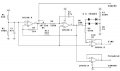
ok so here is the circuit I used and here also is the result from the circuit, the square wave is excellent but the Sine wave needs help lol.....
But at least I have some waves which is more than what I had before, this weekend I am staying in to have a tinker and see if I can work some magic to improve the sine wave, I have already found three mistakes in my wiring so the likely hood of finding another is very high, but then I have come to expect that when I build a project, just carelessness on my part and one of my errors was having the supply switched back to front which cost me a chip.
All op-amps run on single supplies, the only distinction is whether there is a "ground" reference somewhere in between. The point to using two batteries is that the middle connection makes for a convenient ground reference.
All op-amps run on single supplies, the only distinction is whether there is a "ground" reference somewhere in between. The point to using two batteries is that the middle connection makes for a convenient ground reference.
You're misunderstanding the jargon. "Dual supply" tends to mean that the reference voltage for an input signal can not be one of the power rails and must be constructed outside of the op-amp. The reference voltage is usually (but doesn't have to be) set to a point half way between the two power rails. If the power supply is 18V, you can call the power rails 0V and +18V and set the reference voltage at +9V, or you can call the power rails -9V and +9V and define the constructed 0V in between as the voltage reference point. All voltages are relative and you can call them anything you want. The fact remains that the op-amp has just two power pins, + and -.
"Single supply" implies that at least one of the power rails can be used as a signal reference. For instance an LM358 can sense input voltages down to the negative power rail, which is usually called "ground".
A "rail-to-rail" op-amp can sense to both power rails and can use any voltage in between and including them, as a reference voltage for a signal.
You are being confused by the limited definition given here of what constitutes a single supply supply op amp.
It's true that all op amps have a single plus and minus supply connection. But if you ground the minus connection, then standard op amps will have inputs and outputs that will not operate down to ground potential (such as the 741, which can only operate to within a couple volts or so of the rail voltages).
Those are typically operated from a separate plus and minus (or pseudo-ground split supply).
Op amps that are specified as rail-to-rail or single-supply (such as the LM324 which can operate to the negative rail) can be readily used with either a single supply or a dual supply.
With a signal grounded positive supply, they will operate down (or very near) to ground.
Yes and no. With every op-amp, you still have to pay attention to the common-mode range. This is the range of input voltages that can be sensed by the op-amp and can be produced on the outputs. It's very easy to get bitten by your signal passing outside of the allowed input range. A "dual supply" amp cannot sense near either rail. That forces the designer to pay attention to the allowed range, and that's good practice no matter what op-amp you're using. Only "rail-to-rail" allows you to pretty much skip this chore. The 741 you mentioned, if powered at 5V, would have a common mode range of less? than one volt and that narrow range would lie somewhere near +2.5V. And yet we see plenty of folks coming here asking why it's not working for them.
 Facebook
 Google
 GitHub
 Linkedin