XR2206 function generator not working - and the IC heating up

Thread Starter

jytug

Joined Sep 11, 2024
2
Hi all, I'm looking to get a bit more into electronics, my first soldering job (not counting some practice boards) being an XR2206 function generator.
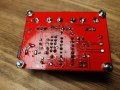
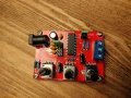
Having soldered it all, following the instructions as well as some youtube tutorials, I could not conceal my disappointment when I found out - the board doesn't work! What happens instead is the IC becomes very hot soon after the power supply is plugged in. The power supply is a standard 9V jack I use for guitar effects.
Could someone with a keen eye and vast experience have look at the pictures and advise:
a) if there's anything glaringly wrong with the solder job or the placement of components;
b) how I could go about debugging such a circuit;

the schematic is available in the link above
 

Attachments

Alec_t

Joined Sep 17, 2013
15,112
There is too much glare in the pic to check your soldering. Please post a sharply-focussed image without glare.
 

be80be

Joined Jul 5, 2008
2,395
chip is in backward looks like its right tho id go with the power supply is wrong the Positive on the pin negative on the barrel and no more then 12 volt dc 9 volt is better
 

schmitt trigger

Joined Jul 12, 2010
2,056
To be your first soldering job, I must say it looks pretty good. I can’t spot any obvious errors. Perhaps the solder holes require to fully filled with solder.

The XR2206 has been obsolete probably for over 20 years. This hasn’t reduced it’s availability, mostly counterfeit devices. Some of these counterfeits will work but may have reduced performance, whereas others simply don’t work at all.
If you decide to substitute the IC, install a socket first.
 
Holy smokes!! I never expected to read about the XR2206 nowadays. I was Exar's Linear IC applications engineer during 1974 to 1976, and I indeed worked with the XR2206 and (if I remember correctly) also the XR2207 and XR2208. That was my first real engineering job. But I have not touched those ICs since, and I am amazed that anyone could get any of those chips nowadays. Exar made those ICs on 2 inch wafers there in Sunnyvale CA. They designed the ICs right there on a light table with drafting tape. I think they were a few $ each back then. That figures to be a pretty expensive IC.
 

DbLoud120

Joined May 26, 2014
99
I have built this same kit and it works as advertised.
The chip is oriented correctly.
If it is getting very hot it is likely damaged.
 

dl324

Joined Mar 30, 2015
18,296
I was Exar's Linear IC applications engineer during 1974 to 1976, and I indeed worked with the XR2206
Can you confirm or deny that the sinewave output always had distortion (spikes)?
I am amazed that anyone could get any of those chips nowadays.
It seems that the chips people are getting now are fakes with a couple of date codes. They don't operate at the maximum voltage of the authentic parts.

A member gave me one of those kits that he assembled. I'll get around to doing some tests someday...
 
I hesitate at the word "always". I think there was significant variation between samples. What most sticks in my mind was asymmetry in the waveform, and I think I sometimes saw spikes at the peaks and valleys. As I remember, the circuit operation seems to start with the timing capacitor which is connected differentially (not one end connected to ground.) There is a significant "switch" which happens when the differential voltage across the timing capacitor stops slewing in one direction and starts slewing in the other direction. Mismatches in the circuitry seem to cause waveform asymmetry and probably also spikes. But I also think that if you have a better sample, the output waveform looks pretty good.

Somewhere I might have a hard copy of the datasheet. This datasheet would have predated my awareness of .pdf files by 25 years and (for that matter) also would have predated the IBM PC by at least a few years.
 

dl324

Joined Mar 30, 2015
18,296
They designed the ICs right there on a light table with drafting tape.
When I worked at HP Labs, I knew some MSEE students at Stanford who were "cutting Ruby" for their designs. I was the system administrator for an Applicon AGS 870 system at the time (late 70's). I was the "mask designer" for some GaAs logic devices that ran at multiple GHz. At that time, the fastest ECL was about 300MHz.
 

Thread Starter

jytug

Joined Sep 11, 2024
2
Thanks everyone for the advice, suggestions and anecdotes. It looks like @ElectricSpidey 's remark was on point. The description in the link I provided states that:
The centre pin is the +ve connection and the outer barrel is the -ve connection.
However, after checking with a multimeter, it looks like the central pin is the negative one, while the barrel is positive! In addition, the power supply also has this symbol on it:
1726184550637.png
which I take to mean that I provided the circuit with "reverse current", possibly damaging the IC! Oh my!

This leads me (a noob) to two questions: how on Earth is this not standardised, and always the same? And, more importantly, how could I have known which type of power supply is expected here?

Edit I also forgot to say that I did in fact skip the socket for the IC, accidentally. I assumed it would make no difference to the circuit, except possibly making it more difficult to replace the IC if needed? (boy do I regret that now)
 

kaindub

Joined Oct 28, 2019
176
OK. So you learnt a lesson
The power plug is not standardised. Neither for polarity nor for voltage.
Always, before powering up check the voltage and polarity of the plugpack.
The chip may have survived.
 

dl324

Joined Mar 30, 2015
18,296
provided the circuit with "reverse current", possibly damaging the IC!
More likely to be definitely than possibly. Reverse power polarity forward biases a parasitic diode and current is only limited by the power source.
This leads me (a noob) to two questions: how on Earth is this not standardised, and always the same? And, more importantly, how could I have known which type of power supply is expected here?
Why would there be a standard? With two terminals, there are two possible polarities and people who will think that one is more logical than another.

Whenever I get something designed in China, I always check for things being backwards. They seem to have a propensity for wiring pots backwards. Sometimes they don't, but that's been the exception in my case. They also like to put things upside down. Maybe that's what the local population expects...

To protect against power not being wired the way you expect, check before applying power.
 

dl324

Joined Mar 30, 2015
18,296
I thought that happened a lot in Australia and other Southern Hemisphere locations?
Some people, regardless of where they are, or are from, just seem to do things backwards. Some Chinese engineers can't even copy something like an Arduino Uno when they have the complete schematic. The only thing they know about LMV358 and LM358 is that one costs less than the other (and the other one has that pesky extra letter)...
 
Do not forget that most of the world's smartphones are being built (and built rather well) in China. As are (as I understand it) some good electric cars.

I do have a cheap (believed to be made in China) soldering iron from MPJA. It does work OK but...
When it quit a few years back I opened it up. There was (if I remember correctly) an LM324 quad op amp inside. The unused amplifier sections were COMPLETELY disconnected. This is a no-no. The correct method is to connect the amplifier output pin to the - input, and connect the + input pin to the ground (negative supply) pin or some other voltage which is in range of the amplifier. But, anyway...

There was also a trimpot on the internal pcb and I tweaked it. Note: This is normally a move made by newbies, but in this case, tweaking the trimpot seemed to be what was needed to get the soldering iron functioning again. Apparently it's adjustment point had become a dead spot of sorts.

I cannot attest to the accuracy of the digital temp readout, but it does seem to be adequately repeatable. I know where to set it to get the soldering results that I want, and that seems to work. Good enough.

I would not expect anyone to be using this soldering iron in a production line for medical or avionics or high rel equipment. But for my work bench it is OK...it is working again... I don't think I tried to wire the amplifier pins, although given that it was in a DIP package that would have been possible (if messy.)
 
Top