Wiring for my robot mower garage door

strantor

Joined Oct 3, 2010
6,875
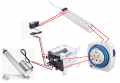
Using two timers only requires a common SPDT 12 volt relay (automotive type) to isolate the timers from each other.
View attachment 300424
This is a clever relay solution that would work, but so would the 4-diode solution; It's just a bit more complicated.

If a relay (or anything) is going to be purchased, it should offer some benefit IMO. In post #8 I provided a different relay solution which eliminates one of the timers and one of the 12V power supplies, which could then be used for other things later.
 

sghioto

Joined Dec 31, 2017
8,737
Agree, the single timer is how I would have done it as well. Since he already has the timers I'm curious to see if the diodes work.
 

Thread Starter

iamzbob

Joined Aug 12, 2023
22
so im coming to the conclusion that i dont have a correct component. therefore im going to change up and use 1 power source and a dpdt switch which i need to order. im looking at this one... https://www.amazon.com/dp/B07FCL6MQY . do you think itll work then using a timer as the trigger to reverse polarity.
 

strantor

Joined Oct 3, 2010
6,875

Thread Starter

iamzbob

Joined Aug 12, 2023
22
i thank both of you for helping me im now following you both thru this site and stantor i just subscribed to your youtube channel. i appreciate both your input. i will post more after i get the component and attempt to get it together. fingers crossed. the only thing more obnoxious than a robot mower is a garage with automatic door for said mower. lolololol.
 

strantor

Joined Oct 3, 2010
6,875
can i just route it thru the power adapter making it 12v
I'm not sure if that's a question or a statement; in either case I don't understand.
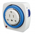
I am assuming your timers are something similar to this:

1691960331584.png

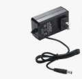
And currently you have plugged into it something like this:

1691960416683.png

Is that correct?
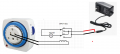
If so, then I'm prosing this:

1691960634023.png

So I don't know what you mean by "route it through the power adapter."
 

strantor

Joined Oct 3, 2010
6,875
He means connecting the output of the timer to the adaptor to get 12 volts for the motor and relay.
That won't work because then the adapter will only get power when the timer is on, and it needs power all the time.

There is no concern about drawing continuous power because the adapter will only draw appreciable power when actuator is moving, and it will stop moving as soon as it hits its internal limits.
 

Thread Starter

iamzbob

Joined Aug 12, 2023
22
ok, i will luk what i come up with. i have 2 power adapters so i could run 1 constant power and 1 off timer but i think either with a 110v dpdt or 12v i can make it work.... i hope
 

Thread Starter

iamzbob

Joined Aug 12, 2023
22
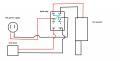
hey all so i got the switch today but ive never used one of these before. i believe this is how i hook it up. my concern is does the relay convert it to 12v dc or do i still need my power adapter. please lmkcircuit.png
 

strantor

Joined Oct 3, 2010
6,875
sorry didnt see this. yes i did get it working thank you so much
Thanks for the update! We who spend our free time helping to solve problems do so in part for the fulfillment of knowing there was a successful outcome, so it is always nice to get that follow-up.
 
Top