Wiring for my robot mower garage door

Thread Starter

iamzbob

Joined Aug 12, 2023
22
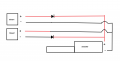
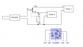
i appologize if this has already been asked but i am automating a mini garage door for my robot mower. i am stuck on the wiring.my setup is with 2 timers so seperate 12v power sources. at a specified time the first timer engages and an actuator raises the door then a minute later that timer shuts off. later the other timer comes on and lowers the door with reverse polarity and a minute later shuts off. seperately both functions work. when i attmpt to wire them together nothing works. ive tried adding a couple recycled diodes to the mix but idk much about diodes. below is essentially what ive tried and it doesnt work. anyadvice would be greatly appreciated. im a dumbo so laymens terms would be appreciated. im thinking this setup isnt possible but im not ready to give up just yet. thanks
 

Attachments

Thread Starter

iamzbob

Joined Aug 12, 2023
22
i appologize if this has already been asked but i am automating a mini garage door for my robot mower. i am stuck on the wiring.my setup is with 2 timers so seperate 12v power sources. at a specified time the first timer engages and an actuator raises the door then a minute later that timer shuts off. later the other timer comes on and lowers the door with reverse polarity and a minute later shuts off. seperately both functions work. when i attmpt to wire them together nothing works. ive tried adding a couple recycled diodes to the mix but idk much about diodes. below is essentially what ive tried and it doesnt work. anyadvice would be greatly appreciated. im a dumbo so laymens terms would be appreciated. im thinking this setup isnt possible but im not ready to give up just yet. thanks
the timers are just plug in yard timers. 24/7 digital timer. i then convert it to dc with an adapter. i looked for a relay but i couldnt find one that would switch automatically.
 

Thread Starter

iamzbob

Joined Aug 12, 2023
22
Does the actuator have internal limit switches?
yes built in. i thought about trying to access them but id prefer not to take the unit apart if i dont have to. ive been thinking about getting some appropriate diodes cause im trying recycled ones and one could be under rated or bad. the reason i think this is because i got half of it to work appropriately, with timer 1 on and timer 2 off and wired like i showed above. then when i switched timer 1 off and timer 2 on it did nothing when it should have reversed the actuator. unless i did the diode wrong that is.
 

strantor

Joined Oct 3, 2010
6,875
yes built in. i thought about trying to access them but id prefer not to take the unit apart if i dont have to. ive been thinking about getting some appropriate diodes cause im trying recycled ones and one could be under rated or bad. the reason i think this is because i got half of it to work appropriately, with timer 1 on and timer 2 off and wired like i showed above. then when i switched timer 1 off and timer 2 on it did nothing when it should have reversed the actuator. unless i did the diode wrong that is.
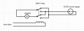
since it has built in limit switches it should be safe to leave power applied to it. You can use just one timer, plus a relay.

1691903515663.png
 

Thread Starter

iamzbob

Joined Aug 12, 2023
22
since it has built in limit switches it should be safe to leave power applied to it. You can use just one timer, plus a relay.

View attachment 300377
i dont understand the symbol next to "from timer", is that an inducter??? the timer is the power source so i don't know how to make that part of the relay.i have a relay from oono for reverse polarity. idk if it would work tho. i added it to my diagram and removed the diodes but idk where to connect the hot. circuit.png
 

Thread Starter

iamzbob

Joined Aug 12, 2023
22
i dont understand the symbol next to "from timer", is that an inducter??? the timer is the power source so i don't know how to make that part of the relay.i have a relay from oono for reverse polarity. idk if it would work tho. i added it to my diagram and removed the diodes but idk where to connect the hot. View attachment 300379
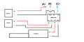
Scratch that labeled things wrong sorry abd i think i maybe figured it out from ur diagram. lmk if im rightcircuit.png
 

strantor

Joined Oct 3, 2010
6,875
i dont understand the symbol next to "from timer", is that an inducter
It's meant to represent the relay coil. When the timer sends 12V to it, the contacts in the relay switch over.

Scratch that labeled things wrong sorry abd i think i maybe figured it out from ur diagram. lmk if im rightView attachment 300381
That might work but depends on the specs of this reversing relay.
What is the coil voltage on it?
What is its behavior when you apply power to FWD and REV inputs at the same time?
 

Thread Starter

iamzbob

Joined Aug 12, 2023
22
Does the timer have NO & NC outputs? Do you have a link to the timer?
no the timer has a 120v output and then i convert that to dc with a power adapter and the relay idk about the coil voltage, when i ordered it i made sure it was 12v but i think its really designed for a toggle switch witch is why i didnt include it originally
 

Thread Starter

iamzbob

Joined Aug 12, 2023
22
@iamzbob what is the mains voltage in your country?
110v
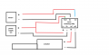
so i tried reversing the diode and that didnt work. i hooked up the relay and it works fine with constant power but i have to manually connect or disconnect the green and black or blue and black connections to make it work. hooking the 12v to the green or blue wires did nothing. so i dont think the relay will work with the other components i have. i think what i need is 2 more diodes so i can fully control each of the inputs direction. that way timer1 isnt getting a back feed from timer 2 on the positive or the negative and vice versa. i dont know if i explained that well enough. my only concern is that timer1 will still ground to timer 2 and vice versa. idk if that will matter.circuit.png
 

sghioto

Joined Dec 31, 2017
8,693
The relay will work when connected correctly. You can try adding the extra diodes and I have a wiring diagram for using a relay.
That reversing relay will not work for this application as it uses external switches.
 
Last edited:

sghioto

Joined Dec 31, 2017
8,693
Using two timers only requires a common SPDT 12 volt relay (automotive type) to isolate the timers from each other.
1691954217287.png
 
Last edited:
Top