will this mosfet driver work?

Thread Starter

Mohaamed Yousry

Joined Sep 23, 2017
14
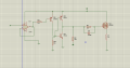
Hi, im trying to build a mosfet driver for my irfp250 , the input signal to the op amp is a 140 kHz square wave,the wave is from a 555 timer running on the same supply as this part of the circuit ,when i tried the totem pole section of the circuit its output is always high regardless of the input signal,any tips on improving my schematic would be helpful , thanks in advance.
 

Attachments

AlbertHall

Joined Jun 4, 2014
12,347
It is likely that either Q2 or Q3 (or both) is blown. Swap the positions of the PNP and the NPN so that their emitters are connected together and drive the MOSFET. You will also need a resistor across the base and emitter of Q4, perhaps 330Ω (depends on the supply voltage).
 

Audioguru

Joined Dec 20, 2007
11,248
The design of a lousy old LM741 is 50 years old and has trouble with frequencies above only 2kHz.

Also its output voltage cannot go high enough to turn off Q4. Therefore the Mosfet will never turn on.

Also, your Mosfet is a follower, not a switch, so its gate must be about 10V higher than your circuit can give it for its output voltage to be anywhere near the supply voltage.
 

Thread Starter

Mohaamed Yousry

Joined Sep 23, 2017
14
It is likely that either Q2 or Q3 (or both) is blown. Swap the positions of the PNP and the NPN so that their emitters are connected together and drive the MOSFET. You will also need a resistor across the base and emitter of Q4, perhaps 330Ω (depends on the supply voltage).
the purpose of that resistor would be a pull up for base of Q4? how do i choose the correct value?
Also its output voltage cannot go high enough to turn off Q4. Therefore the Mosfet will never turn on.
now that you mention it, my op amp output is attenuated so should i use the signal to bias Q4 directly?
Also, your Mosfet is a follower, not a switch, so its gate must be about 10V higher than your circuit can give it for its output voltage to be anywhere near the supply voltage.
I'm building 4 of these mosfet drivers to drive a mosfet H bridge , do i need to switch the top mosfets with p channel instead?
 

AlbertHall

Joined Jun 4, 2014
12,347
the purpose of that resistor would be a pull up for base of Q4? how do i choose the correct value?
To turn off Q4 the output of the '741 would have to get within 1V of the positive supply which it can't do. The additional resistor allows Q4 to turn off with lower voltages from the '741.
 

shortbus

Joined Sep 30, 2009
10,045
Don't quite understand why, unless this is a school project, anyone would even try to make their own gate driver instead of using a standard off the shelf driver chip. Takes less components, and even less board space. And even less effort.
 

OBW0549

Joined Mar 2, 2015
3,566
I'm building 4 of these mosfet drivers to drive a mosfet H bridge , do i need to switch the top mosfets with p channel instead?
Forget about building your own MOSFET gate drivers; as others have pointed out, the circuit you posted has several serious (and in a couple of cases, fatal) problems.

Instead, do what @shortbus suggested: use a MOSFET driver IC. They're inexpensive, readily available, take up much less PCB space than what you're trying to design, and they work much better than anything you can build. Microchip's MCP1406/1407 would be a good one to try.
 

Thread Starter

Mohaamed Yousry

Joined Sep 23, 2017
14
Don't quite understand why, unless this is a school project, anyone would even try to make their own gate driver instead of using a standard off the shelf driver chip. Takes less components, and even less board space. And even less effort.
Although i'd love to use one of these mosfet driver ics but they don't sell them at any electronics store from where i live,basically all they sell are 50 year old stuff llike the 741 op amp , so i'm stuck with building my own gate driver or i might just give up.
 

ian field

Joined Oct 27, 2012
6,536
The design of a lousy old LM741 is 50 years old and has trouble with frequencies above only 2kHz.

Also its output voltage cannot go high enough to turn off Q4. Therefore the Mosfet will never turn on.

Also, your Mosfet is a follower, not a switch, so its gate must be about 10V higher than your circuit can give it for its output voltage to be anywhere near the supply voltage.
There are much faster modern op amps, but I probably wouldn't bother using one in that application.
 
Top