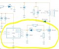
it's kinda like a slayer exciter transformer I think, not exactly sure what to call it. Rather than connect the secondary coil ground to the base of the transistor, I'm trying to build one that uses and antenna to capture the resonant frequency and then run it through the 74AHCT, then either into the MOSFET driver to transistor or from 74AHCT to base of transistor. Anyway I checked the specs of the transistor I'm running, the MOSFET driver, and other parts in the circuit and they can handle the frequency.
Do you have an English data sheet? My Japanese is not good.
IC=1A you probably have a gain of 30. You need 30mA minimum Base current.
At 800mA Ic your Ft is falling fast. 20mhz is fast at 1A.
Are you using the transistor in linear mode or full on/off? Please tell us what are doing.
Are you OK burning 1 Watt in the Gate drive?
Many "gate drivers" are built for Amps for 100nS not for 50% of the time. Might get hot.
Running this fast you need to drive the Base off. It probably needs pulled down to turn off the transistor in time.
I have never used this part.
Show us what you are thinking about for the Base drive circuit.
Right now, I'm experimenting, no hard set schematic. In attachments is 2SC2336A datasheet in English. I'm not driving the transistor at 1A, should have specified. 1A or slightly less is the total current I'm aiming for in the circuit including the load on the primary coil.
I want the transistor to turn on and off.
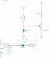
In a previous project used a MOSFET driver to drive the MOSFET gate and was wondering if this same circuit would work for a transistor. MOSFET Driver circuit diagram from previous project in attachments.
The MOSFET's Gate pulls no current most of the time. The only time current flows in the Gate is charging up the internal capacitors. A Transistor needs current to turn it on, not voltage.
The MOSFET turns on/off at about 3 volts. (depends on what type of MOSFET) A transistor turns on/off at about 0.65 volts. It is not affected by voltage but current.
The MOSFET is turned switch on by current flowing through 47 ohms. It is turned off by current in (47//47) ohms. (parallel) At turn-on TL4426-6 is at 12V and pin-7 will be about 11V. The Gate will be at about 3V. 8V & 47 ohms gives the Gate current at the switching point. The turn off flows from two paths. TL4426-3 is at 0V, Pin-7 might be at 1V, Gate is at 3V. (2V & 47 ohms) This is one path. The second path is Pin-1 at 1V, 1N914 drops 0.7V at high current. (1.3V & 47 ohms)
Now look at the case for a transistor. For on we have Pin-7 at 11V. (about) The Base current will be found by 11V-0.7V=10.3V & 37 ohms. Now the turn off current is a problem. AT DC there is no Base current. But we must discharge the internal capacitors and also there is a storage delay effect that needs to be discharged. At the turn off point TL4426-Pin-7 will be near 0V or if current discharge is flowing, maybe about 0.5V. So the current is through 47 ohms is almost zero, because both ends of the resistor are so close to 0V. The 1N914 will see no current and its resistor will see no current. My point is that the Base is not being driven off, which we do at high speeds, but it is almost left to float down.
If you are going to do this, Connect TL4426 Pins 2&4 together, and Pins 5 & 7 together. This will double the drive current of the IC. (less heat) the output pins will be closer to the supply voltages.
Short out 1N914, it is not helping. Maybe put a small cap across 47 ohms to speed up the edges.
I don't see the need for 10k.
I normally do not put a capacitor on the output of a Gate driver. (1000pF)
Yes, it will work. I just want you to know how and why.
The MOSFET's Gate pulls no current most of the time. The only time current flows in the Gate is charging up the internal capacitors. A Transistor needs current to turn it on, not voltage.
The MOSFET turns on/off at about 3 volts. (depends on what type of MOSFET) A transistor turns on/off at about 0.65 volts. It is not affected by voltage but current.
The MOSFET is turned switch on by current flowing through 47 ohms. It is turned off by current in (47//47) ohms. (parallel) At turn-on TL4426-6 is at 12V and pin-7 will be about 11V. The Gate will be at about 3V. 8V & 47 ohms gives the Gate current at the switching point. The turn off flows from two paths. TL4426-3 is at 0V, Pin-7 might be at 1V, Gate is at 3V. (2V & 47 ohms) This is one path. The second path is Pin-1 at 1V, 1N914 drops 0.7V at high current. (1.3V & 47 ohms)
Now look at the case for a transistor. For on we have Pin-7 at 11V. (about) The Base current will be found by 11V-0.7V=10.3V & 37 ohms. Now the turn off current is a problem. AT DC there is no Base current. But we must discharge the internal capacitors and also there is a storage delay effect that needs to be discharged. At the turn off point TL4426-Pin-7 will be near 0V or if current discharge is flowing, maybe about 0.5V. So the current is through 47 ohms is almost zero, because both ends of the resistor are so close to 0V. The 1N914 will see no current and its resistor will see no current. My point is that the Base is not being driven off, which we do at high speeds, but it is almost left to float down.
View attachment 357740
If you are going to do this, Connect TL4426 Pins 2&4 together, and Pins 5 & 7 together. This will double the drive current of the IC. (less heat) the output pins will be closer to the supply voltages.
Short out 1N914, it is not helping. Maybe put a small cap across 47 ohms to speed up the edges.
I don't see the need for 10k.
I normally do not put a capacitor on the output of a Gate driver. (1000pF)
Yes, it will work. I just want you to know how and why.
I dont know what I was thinking earlier posting this as a comparison as the circuit I'm running isn't entirely like this and the way it's done is completely different. Sorry for wasting your time. Here's a much better circuit idea.
 Facebook
 Google
 GitHub
 Linkedin