Why does this simple amp sound so good?

Bordodynov

Joined May 20, 2015
3,431
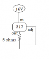
No, it makes no sense. I just have several versions of the stabilizer model and conditional suffixes distinguish them. The value of 5.6 of these resistors determines the mode current. Increase them and the current will decrease. The lower resistor is similar to an emitter resistor in a cascade with a common emitter. This is negative feedback. To increase the steepness of the cascade (to remove negative feedback on alternating current), the resistor is shunted by the capacitor.
 

Hextejas

Joined Sep 29, 2017
187
Hi,
designed this amp, it sound very good but would like to understand its strength and weakness.
The intent was to design a class A amp using a constant current source (LM317) to compensate for a cheap voltage source.
Appreciate any help.

If anyone else builds it would love to hear their feedback.
Thanks

Edited on 12/9/2017:
After some good feedback by members (especially Bordodynov) replaced the IRF530 mosfet with 2N7000 and the freq response is now very flat from 40 - 20KHz. If some is interested in building this amp please use 2n7000 or some other mosfet with low input capacitance. It works with a BJT too. Please find the an updated screen shot from LTSpice.
Thanks.
Well, being totally new to this sport, I am trying to build this beast and I can't figure out, for the lm317, which is input, output, and adj.
Can anyone please clarify for me ?
 

Hextejas

Joined Sep 29, 2017
187
The pins on a 317 are different, depending on the package, and maybe the manufacturer. The only sure answer is to look up the datasheet for exactly which chip you bought.
http://datasheetcatalog.com/
Thank you 12, but figuring out which are the input, output, and adj pins on the above schematic is what I am asking.
I asked the OP via email about 2 weeks ago, but he has not answered.
So the pins shown and my guesses are:
Into the TIP 122 = ? Out ?
To the 115k resistor = ? Adj ?
From the 16V = ? In ?
 
Hi,
designed this amp, it sound very good but would like to understand its strength and weakness.
The intent was to design a class A amp using a constant current source (LM317) to compensate for a cheap voltage source.
Appreciate any help.

If anyone else builds it would love to hear their feedback.
Thanks

Edited on 12/9/2017:
After some good feedback by members (especially Bordodynov) replaced the IRF530 mosfet with 2N7000 and the freq response is now very flat from 40 - 20KHz. If some is interested in building this amp please use 2n7000 or some other mosfet with low input capacitance. It works with a BJT too. Please find the an updated screen shot from LTSpice.
Thanks.
 
Built this, it sounds great. Just asking, how do you calculate what supply voltage you need and the output swings? I probed it with a scope and got about 1.5V of swing running it at a 600mA current before it started clipping softly.
 

DickCappels

Joined Aug 21, 2008
10,661
Just asking, how do you calculate what supply voltage you need and the output swings? (some text removed for clarity)
In order to come up with a good approximation you need to know three things:

• The P-P voltage you desire

• The voltage you need to have across the positive output device(s) when supplying the needed current.

• The voltage you need to have across the negative output device(s) when supplying the needed current.

Add all three voltages together and then carefully bias the quiescent operating point of the output to the midpoint of the dynamic range of the output.
 

MSFTF

Joined Aug 11, 2017
33
Thank you 12, but figuring out which are the input, output, and adj pins on the above schematic is what I am asking.
I asked the OP via email about 2 weeks ago, but he has not answered.
So the pins shown and my guesses are:
Into the TIP 122 = ? Out ?
To the 115k resistor = ? Adj ?
From the 16V = ? In ?
I figured out the pins on a three terminal regulator with a meter using diode and resistance checks. I recall the output has an internal diode going back to the input. The "ground" connection has no diode reading to either of the two other pins. That was enough information and it discerned what the three pins were.
 

Audioguru

Joined Dec 20, 2007
11,248
The datasheet from a manufacturer for a voltage regulator, darlington transistor or ordinary transistor and IC is online.
The datasheet for the LM317 and TIP122 show the pins on the first page of the datasheet. LM317= ADJ, OUT, IN and TIP122= Base, Collector. Emitter.
The datasheet tells you everything about it and you should have the datasheets.
 

Audioguru

Joined Dec 20, 2007
11,248
Someone was saying the pin outs aren't always the same.
The pinouts on a datasheet from a Western manufacturer are always correct. Chinese datasheets written in Engrish might have a translation error.

Of course different parts have different pinouts like an American 2N3904, a European BC549 and an Oriental 2SC945.
 

Thread Starter

iinself

Joined Jan 18, 2013
98
Built this, it sounds great. Just asking, how do you calculate what supply voltage you need and the output swings? I probed it with a scope and got about 1.5V of swing running it at a 600mA current before it started clipping softly.
Just play with the feedback resistor to increase the swing, since that is only parameter to play it does not take too long. In my case I get around 12V p-p for supply of 17v, LM317 supplies around 250mA. Please take a look at this slightly modified circuit, I like this better. Got rid of the darlington and reduced feedback. Various transistors can be tried out, the output transistor needs to be able to handle the power, don't forget the heatsink. I think you will like the sound of it :)
 

Attachments

Last edited:

Thread Starter

iinself

Joined Jan 18, 2013
98
Well, being totally new to this sport, I am trying to build this beast and I can't figure out, for the lm317, which is input, output, and adj.
Can anyone please clarify for me ?
Sorry, I just try to keep the diagram simple and did not draw the LM317 current source part of the circuit, please take a look at post #55 above.
 
Top