And I really like this schematic.
It is a good scheme.
Strength:
The LM317 protects the power circuit limiting to a constant current
Even if you do short circuit between E and C of TIP122 do not burn.
Weakness:
No reaction(feedback). Larger distortions.
Slew rate not very good.
If you like how it sounds it is the most important.
what you can improve:
Take the IFR530 aside which is useless there and comparable as a price with TIP122.
TIP122 is darlington and has enough amplification.
The IRF530 added linearity and clarity so little that I think is useless
Hi iinself.
The output impedance of your preamp is 4.7kOhm. This affects the overall frequency response.
I advise you to determine the frequency response for a complete set of circuits (tube preamplifier + your amplifier). Or use only your amplifier + additional series resistor 4.7kΩ.
Stand corrected: The freq response does fall off but not as sharply as indicated by the simulation. Here are some values I measured directly across the speaker terminals. I am not sure about the db calculation so:
From your data, I see that the frequency range is 100Hz - 5000Hz. For the transfer of voice (speech), this is more than enough. I just hinted that the frequency range would be about the same as you got. For frequency expansion, a first transistor with smaller capacitance is needed.
From your data, I see that the frequency range is 100Hz - 5000Hz. For the transfer of voice (speech), this is more than enough. I just hinted that the frequency range would be about the same as you got. For frequency expansion, a first transistor with smaller capacitance is needed.
And I really like this schematic.
It is a good scheme.
Strength:
The LM317 protects the power circuit limiting to a constant current
Even if you do short circuit between E and C of TIP122 do not burn.
Weakness:
No reaction(feedback). Larger distortions.
Slew rate not very good.
If you like how it sounds it is the most important.
what you can improve:
Take the IFR530 aside which is useless there and comparable as a price with TIP122.
TIP122 is darlington and has enough amplification.
The IRF530 added linearity and clarity so little that I think is useless
Hi, unable to make it work by removing the IRF530. I have used a 2n7000 which has added a lot of clarity and good freq response, see first post for details. thanks
Its gain is affected by the signal source impedance. Since the current is only 0.25A then the maximum output power to the 6 ohm speaker is only about 0.25A x 6 ohms= 1.5W peak which is 0.75W RMS but its heating is 0.25A x 12V= 3W all the time, even with no output.
Its gain is affected by the signal source impedance. Since the current is only 0.25A then the maximum output power to the 6 ohm speaker is only about 0.25A x 6 ohms= 1.5W peak which is 0.75W RMS but its heating is 0.25A x 12V= 3W all the time, even with no output.
Thanks. I understand class A max efficiency can be only 50%. In my case it is probably much less. The sound is nevertheless very loud for a 15X15 ft room.
I am unable to make the voltage swing past 7V p-p, is there any way I can do that? Any ideas on how I can make the amp independent of the source impedance?
I am unable to make the voltage swing past 7V p-p, is there any way I can do that? Any ideas on how I can make the amp independent of the source impedance?
If you increase the supply voltage and change the bias resistor value then the output voltage swing and heating will be more. Many ordinary class-AB amplifiers are bridged so they use two amplifiers, each amplifier driving one wire of the speaker, but the amplifiers have opposite phase so that the voltage swing across the speaker is almost doubled then the speaker current is also almost doubled for about 3.5 time the output power of a single amplifier with the same supply voltage and speaker.
Add an input buffer amplifier to isolate the negative feedback from the signal source.
The lower stabilizer chip works like a transistor and amplifies the voltage. The upper chip acts as a dynamic load and a voltage follower. Since the slope of the microcircuit is very large (much larger than that of the transistor), negative feedback is used to stabilize the gain. The gain is equal to the ratio of the values of the resistors R6 / R5 = 10.
The input impedance of the amplifier is 10 kOhm. The output impedance of the amplifier is much lower than the load resistance (the damping coefficient is large). The upper microcircuit of the stabilizer works similarly to the scheme of a transistor with a common collector. The lower stabilizer chip works similarly to a common-emitter transistor.
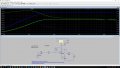
I made a calculation for the signal with two different frequencies. This is 1 kHz and 10 kHz. As can be seen from the pictures, the amplitude of the output voltage for these cases is practically equal to (2 V).
I did not optimize the electronic circuit for DC modes. How to draw an electronic circuit so it left it.
I think that this circuit has good reproducibility of parameters (important for a stereo amplifier), in contrast to the use of a field effect transistor having a large spread in direct current.
The lower stabilizer chip works like a transistor and amplifies the voltage. The upper chip acts as a dynamic load and a voltage follower. Since the slope of the microcircuit is very large (much larger than that of the transistor), negative feedback is used to stabilize the gain. The gain is equal to the ratio of the values of the resistors R6 / R5 = 10.
The input impedance of the amplifier is 10 kOhm. The output impedance of the amplifier is much lower than the load resistance (the damping coefficient is large). The upper microcircuit of the stabilizer works similarly to the scheme of a transistor with a common collector. The lower stabilizer chip works similarly to a common-emitter transistor.
I made a calculation for the signal with two different frequencies. This is 1 kHz and 10 kHz. As can be seen from the pictures, the amplitude of the output voltage for these cases is practically equal to (2 V).
I did not optimize the electronic circuit for DC modes. How to draw an electronic circuit so it left it.
I think that this circuit has good reproducibility of parameters (important for a stereo amplifier), in contrast to the use of a field effect transistor having a large spread in direct current.
I think it sounds good because its class-A heat makes you feel warm in winter.
Since its maximum output is only 0.75W then even if it produces awful 2% distortion the distortion will not be loud enough to hear it.
Years ago I put an LM390 amplifier IC in an old clock radio and its 1W sounds great into an external 2-way speaker. An LM390 is like an LM386 in a 14 pins case and has external bootstrapping for higher output power. Since it is class-AB it produces no heat when idling and gets just a little warm at full power.
I am new to this and am thinking about trying to build this.
For the LM317, there is a -12 suffix. Does it have any special meaning ?
Also I noticed that R2 and R8 are 5.6. Is that correct ? I am sure that I don't have any resistors that are that small.
 Facebook
 Google
 GitHub
 Linkedin
")