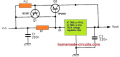
Why does the voltage sag above 1 A in this power supply?

JohnSan

Joined Sep 15, 2018
130
Why use more components than necessary?
The 7912 is rated at 1.5A and 15W.
A simple 3.3R 10W series resistor holds its power dissipation at around 6W at 1.5A. Well within its rating. It needs an appropriate heatsink and the capacitors must be mounted close to it. Preferably on its pins.
Why complicate it with another transistor? It will also need mounting to a heatsink, connecting and specifying correctly, for what gain?
The supply is what the TS already has, so it is what it is.
I guess the load will not be 1.5A continuous anyway?
 
Last edited:

MisterBill2

Joined Jan 23, 2018
28,011
I have experienced megahertz frequency and high amplitude oscillations from using a series resistor ahead of a 7812 regulator. For that reason I suggest that it may work out as an interesting experiment. I do not recommend a series resistor for that reason. I chose to avoid a second episode. Put at least half of the dissipation in the pass transistor.
 

DickCappels

Joined Aug 21, 2008
10,662
This is all you need unless you want to make it into a switching regulator.
1758445283080.png

When the IR drop. across R1 exceeds the VBE of the TIP2955, the TIP2955 starts to conduct. The voltage regulator inside the 7812 is still "in control" of the output voltage.

Since the normal current limit circuit inside the LM7812 has been bypassed an additional transistor (the BC557) puts the circuit into current limit as the IR drop across R2 approaches the VBE of Q1.

Now, change the regulator chip to a negative voltage regulator like the 7912 and the external transistors to PNP. Pay attention to the polarity of polarized capacitors

Change Q2 to NPN type, such as 2N2222 for Q1 and to a higher current rated NPN like 2N3055 and you're done.
 
Last edited:

Irving

Joined Jan 30, 2016
5,195
I prefer the MOSFET version of this, with an N-channel and LM337 for the -ve regulator. Because a MOSFET is voltage rather than current driven it can operate with a much larger resistor and therefore a larger differential between IC and MOSFET currents..
 

Hamlet

Joined Jun 10, 2015
560
without massive heatsink, regulator will reach thermal limit and because of this protective mechanism, regulator will lower the current, when that happens, transistor too will turn off. and then result is that output voltage sags. if you want to use linear regulators be aware of dissipated heat. you can increase R1 value so that regulator current is small and transistor kicks in sooner. then you may need small or no heatsink on the regulator but heatsink on transistor would need to be even larger.

with R1 value such as 5.6 Ohm, transistor would start conducting when 0.6V/5.6Ohm = 0.1 A.
and if regulator only handles 0.1A, then (21-12)V * 0.1A = 0.9W. but transistor would need to handle remaining 1.4A
(21-12)V*1.4A=12.6W.

if you do not want to worry about massive heatsinks, use switching regulator or at least make sure that voltage difference is sufficiently small (2.5-3V, not 9V). when voltage differential is large, switching regulators are strongly preferred.

btw. with couple of additional parts (diode and inductor) one can convince linear regulators to work as switching regulators. this is typical example which is showing positive regulator but this can be adapted to work as negative type.
View attachment 356140

so in your case that could look something like this

View attachment 356142
I like that switcher.
 
Top