 Facebook
 Google
 GitHub
 Linkedin
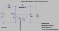
With Vin=12V and a 60% duty cycle, I was expecting a 30V output. But Instead I got a Vout=27V. I thought it was because of the diode, but its forward voltage drop is only 0.2V. So I tweaked everything and I noticed I had to make Rload=80 to get a 30V output. Why can't Vout=30V when Rload=50?


Attachments
-
 23 KB Views: 3


