Facebook
 Google
 GitHub
 Linkedin
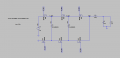
I'm studying FCML converters, especially the 4-level / 3-cell topology. It's clear that when the flying capacitors become imbalanced (e.g., one undervolted), the switching node voltages deviate from their expected levels.
I’ve read that the output inductor plays a key role in naturally restoring capacitor balance, acting somewhat like an integral controller. However, I'm struggling to intuitively understand how the inductor's current slope becomes a self-correcting mechanism.
My current understanding:
Could anyone explain this concept in simple terms, or point me to visual/numerical resources that demonstrate this?
Thanks in advance!
I’ve read that the output inductor plays a key role in naturally restoring capacitor balance, acting somewhat like an integral controller. However, I'm struggling to intuitively understand how the inductor's current slope becomes a self-correcting mechanism.
My current understanding:
- Capacitor imbalance leads to incorrect switching node voltages.
- This creates a voltage across the inductor.
- The inductor responds with a current slope.
- That current redistributes charge between capacitors during different phases.
Could anyone explain this concept in simple terms, or point me to visual/numerical resources that demonstrate this?
Thanks in advance!