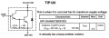
We talked about a TIP120 darlington and various Mosfets. Which one produces an output of 0.9V when the current is 5A?
Maybe it gets so hot that it conducts more than when it is cooler.
Actually I double checked the voltage readings, and confirmed them. I also changed out the TIP120 with another TIP120 and got virtually identical readings. Then I decided to disconnect the PIR sensor, so the only wiring is the +12V lead to the 300 LED strip, then from the LED strip to the TIP120 collector. The TIP120 base was disconnected, and the TIP120 emitter was of course tied to ground. I still get 5V for Vce. Finally, I went ahead and grounded the TIP120 base. So if you look at the circuit at the top of this thread, all you have is the right side of the circuit: +12V to LED string to TIP120 collector to base to ground. And Vce = 5V. Certainly I do not know how to explain it, but that is in fact what it is.
Regardomg the 0.9 Vce and 5 amps, I can't be sure if the current really is 5A, but I do know that the LED string is pretty bright, so I expect several amps are flowing.
1. A 300 LED strip is gonna leak, so it appears as a voltage source, current source, resistance, or some combination. Whatever - electrons are available for action.
2. A DMM has a typical input resistance of 10 M.
3. A good-but-turned-off power darlington will have a C-E impedance of some kind that appears in parallel with the DMM input, shunting away some of the available electrons.
Within all of that hand-waving, I have no problem with the *possibility* that the transistor is good and the reading is correct.
FYI _ I got a box of IRL8721 in the mail today (10 for $10 w/ free shipping). Of course, all I need is one, but they are fun to play with. Anyway, changed out the TIP120 with the IRL8721 and it works like a champ! No heating at all. Also, an additional note to the observations above, when using the TIP120, even in the off-state, there was sufficient current to ever so lightly illuminate the LED string - With the IRL8721, it appears completely dark in the off state, and just as bright in the ON state, as least to my eye.
FYI _ I got a box of IRL8721 in the mail today (10 for $10 w/ free shipping). Of course, all I need is one, but they are fun to play with. Anyway, changed out the TIP120 with the IRL8721 and it works like a champ! No heating at all. Also, an additional note to the observations above, when using the TIP120, even in the off-state, there was sufficient current to ever so lightly illuminate the LED string - With the IRL8721, it appears completely dark in the off state, and just as bright in the ON state, as least to my eye.
I'm glad to hear it's working. Out of curiosity, did you simply drop the IRL8721 into your original circuit from the first post, or did you make other changes, like maybe adding a pull down resistor from Gate pin to Source pin on the MOSFET?
There have been a few PIR questions here lately that made me curious about some of the subtleties of making these circuits behave.
I just substituted the MOSFET for the Darlington. Changed the resistor to 470 ohm for current limiting in case the MOSFET fails closed someday. I did not add a pulldown resistor (but in retrospect that sounds like a good idea). The MOSFET barely shows any temperature rise when flowing all the current, as least none almost perceivable with my fingers.
I just substituted the MOSFET for the Darlington. Changed the resistor to 470 ohm for current limiting in case the MOSFET fails closed someday. I did not add a pulldown resistor (but in retrospect that sounds like a good idea). The MOSFET barely shows any temperature rise when flowing all the current, as least none almost perceivable with my fingers.
Cool, thanks for the update. I'm not at all surprised that the MOSFET is running nice and cool. The only part I was wondering about was whether or not a pull-down was required to achieve a good, solid "off" state. I know nothing about the PIR circuit output stage - depending on factors like leakage current, push-pull vs. other output types, etc. it might or might not have needed a pull-down. I have a sneaking suspicion that a pull-down would've fixed the always-slightly-on aspect of your earlier Darlington attempt, but that's a moot point since it still wouldn't help with the massive heat dissipation issues.
Anyway, I'm not second guessing your circuit at all, and I have no idea if there's any benefit to adding the pull-down, given that you already have it working to your satisfaction without it. If you had needed the pull-down to make the MOSFET work at all, that might've told me something more concrete about the PIR output. The fact that things work without it isn't quite as revealing. Regardless, I'm glad your circuit is working now, and thanks again for answering my follow-up question.
I did go back and set it up again with the TIP120, verified that we get very dim LEDs lit when in the OFF state (w/o a pulldown resistor), and then I added a 4.7Kohm pull-down (only one available) and also got the same result. I sort of expected that anyway -- yes, now we know the base was pulled down to 0V, but there is some leakage across the collector/emitter.
The TIP120 already has a base-emitter resistor. I think your leakage problem is because your heatsink is not working properly.
Is it too small? Did you forget to use heatsink compound grease?
The TIP120 already has a base-emitter resistor. I think your leakage problem is because your heatsink is not working properly.
Is it too small? Did you forget to use heatsink compound grease?
The heatsink is probably too small. See comment #38 in this thread for a photo. I didn't have thermal grease, but it does have a gray "pad" that mounts between the TIP120 and the aluminum, which I assume performs some of the same function. Thanks for the info on the embedded BE resistor. Good to know. Edit: Actually, the gray pad is an isolater so that the back of the TIP120 and the heat sink are the electrically isolated. But to be clear, the heat sink is what I am touching when I see the TIP120 get hot. The TIP120 itself doesn't seem any hotter than the heat sink. I agree that thermal grease would be a good idea regardless.
The grey pad probably is a Sil-Pad or something similar, a flexible, thermally conducting, electrically isolating material. It is not as good a thermal conductor as a thin layer of thermal grease, but it is an excellent tradeoff of easy to use, not messy, and not fragile,
 Facebook
 Google
 GitHub
 Linkedin