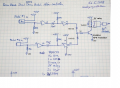
Where to add a sensitivity pot in my circuit

sghioto

Joined Dec 31, 2017
8,737
Yeah
I assume it would be fine but could I used a polarized .1uF cap
Sure that is OK. Sorry for the delay I missed your last two post until just now for some reason. So a defective pot, huh didn't see that one coming!:eek:
EDIT: Sometimes when the power is first applied the 555 will trigger but shuts off normally after the delay time has elapsed. With an open pot the capacitor has no way to charge so the output will stay high forever.
SG
 
Last edited:

Thread Starter

Serik21

Joined Feb 23, 2018
62
I just read the edit. That's kind of how I figured it out. I tested the 3rd circuit before I attached the jacks or pots with the same result. I had a thought about the lack of voltage on pin 6 was maybe the issue. So I connected it to 5v with just the 1k resistor and it was good .So that's when I swapped out that pot.

I noticed that about the 555 triggering when it powered up too. When I had it hooked up to my kick pad and powered it up I got an instant kick .
 
Last edited:

Thread Starter

Serik21

Joined Feb 23, 2018
62
Hey, not exactly on this topic but i would like to build this circuit next but i have a few questions about it. For one, for some reason there is a +5v next to the ground symbol for the top leg of input jack #1, that shouldnt be there should it? In the decription he says pin 14 of the 74HC14 gets +5v and pin 7 goes to ground.

I assume the inverter (NON gates) symbols are just showing me which legs of the 74HC14 to connect the labeled components to?

And last the relay at the output jack. Its just a simple SPST 5V relay, how would i wire that up? would i just tie the leg from the transistor it shows to the coil of the relay with a diode between it and the ground side of the coil? and then wire both ends of the mono output jack / cable to C and NO legs?


The full description of the project is here if that helps http://imakeprojects.com/Projects/rock-band-dual-bass-drums-controller/

thanks in advance!!!
 
Last edited:

Thread Starter

Serik21

Joined Feb 23, 2018
62
Thanks so much for the updated schematic!!

Hey, another question about the original circuit. I've built another one and this one is behaving strangely as well . When I send the pulse from my kick pedal through the circuit the output pulse stays on for a long time, anywhere from 5 - 30 seconds and voltage sits at pin 3 of the 555. Is it a bad transistor? Or perhaps the pulse width pot again? Any ideas

Thanks :)
 
Last edited:

Thread Starter

Serik21

Joined Feb 23, 2018
62
Sure sounds like the pot again.
SG
It was, I forgot to come back and edit it. :p

Also, on the new circuit you fixed the schematic for me do I need to put +5v to pin 14 and ground to pin 7 as well as mentioned in the description on the project page?
 

Thread Starter

Serik21

Joined Feb 23, 2018
62
Hey, so the description of the new circuit mentioned I could use just about any diode. Is a 1N4148 fine?

And I don't have 120 ohm resistors, I assume wiring a 100 ohm and a 20 ohm in series will serve the purpose?
 
Last edited:

sghioto

Joined Dec 31, 2017
8,737
1N4148 is fine for the two diodes coming from the 74HC14. I would use a 1N4002 for the diode across the relay coil. The resistor value is determined by the amount of current the relay draws and the DC gain of the transistor. In this case a value of 1K should be adequate for most 5 volt relays
SG
 

Thread Starter

Serik21

Joined Feb 23, 2018
62
Built the new circuit tonight and it works like a charm! Thanks again!

Just out of curiosity why is there a diode across the coil of the relay? To keep from damaging the transistor?
 

Thread Starter

Serik21

Joined Feb 23, 2018
62
Hey SG,

Would there be a way to add a pulse width adjustment to this new circuit at all? I'm finding the pulses sent through the pedal trigger stay on too long and make it hard to do two quick hits in a row.

Thanks in advance!
 
Top