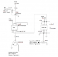
Where to add a sensitivity pot in my circuit

Thread Starter

Serik21

Joined Feb 23, 2018
62
Hello folks!

I'm building the attached circuit to convert the voltage signal from a piezo in an electronic drum head to a simple on/off signal.

My question is where could I insert a pot in the circuit to adjust the threshold of how much voltage from the piezo (ie how hard you would have to hit the drum ) to send the signal through the circuit? What basically would would end up being a sensitivity adjustment.


I appreciate your time and efforts greatly!

Thank you!
 

Thread Starter

Serik21

Joined Feb 23, 2018
62
Since the kick trigger is outputting voltage through the tip of the mono jack, would I wire the tip to the first leg of the pot, the sweeper to pin 2 of the LM386 and the 3rd leg of the pot to ground?

And since the voltage coming out of the kick trigger piezo is so negligible I would want to use a small pot, 1k? 10k? I have 100k pots but I feel like there would be a very small adjustable range before you would lose all the voltage .
 

sghioto

Joined Dec 31, 2017
8,673
Since the kick trigger is outputting voltage through the tip of the mono jack, would I wire the tip to the first leg of the pot, the sweeper to pin 2 of the LM386 and the 3rd leg of the pot to ground?
That would be correct. 100K pot should work OK as well.
SG
 

sghioto

Joined Dec 31, 2017
8,673
I noticed on the schematic pin #4 of the 555 is shown connected to pin #2. It should be connected to pin #8 or 5 volts. Also suggest a few extra components to clean up the signal from the LM386 as shown in the attachment.
SG
EEE drum head one shot.png
 
Last edited:

Thread Starter

Serik21

Joined Feb 23, 2018
62
I noticed on the schematic pin #4 of the 555 is shown connected to pin #2. It should be connected to pin #8 or 5 volts.
SG
So you're staying the 5v going to pin 2 via a 100k resistor will not be enough? So I should tie leg 4 directly to the 5v rail?
 

sghioto

Joined Dec 31, 2017
8,673
So you're staying the 5v going to pin 2 via a 100k resistor will not be enough? So I should tie leg 4 directly to the 5v rail?
I'm saying that Pin 4 is the reset pin and is normally connected to 5 volts and should not be connected to pin 2. Pin 2 doesn't need the 100K to 5 volts because the output of the LM386 pin 5 is biased at half the supply or 2.5 volts. See edited post #5
SG
 

ScottWang

Joined Aug 23, 2012
7,503
I noticed on the schematic pin #4 of the 555 is shown connected to pin #2. It should be connected to pin #8 or 5 volts. Also suggest a few extra components to clean up the signal from the LM386 as shown in the attachment.
SG
View attachment 147008
It still there is no any resistor in series between pin 3 of 555 and bjt(2N3904) and then it will damage the bjt.
 

Thread Starter

Serik21

Joined Feb 23, 2018
62
I'm saying that Pin 4 is the reset pin and is normally connected to 5 volts and should not be connected to pin 2. Pin 2 doesn't need the 100K to 5 volts because the output of the LM386 pin 5 is biased at half the supply or 2.5 volts. See edited post #5
SG
So I'm still fairly new at circuit building. The caps you added, does it matter what voltage they are as long as the are larger than 5v? Or there a specific voltage I should be getting .
 

ScottWang

Joined Aug 23, 2012
7,503
So would I multimeter across the circuit from pin 3 of 555 to ground and test resistance when striking the piezo?

And then would I match the resistor value?
What kind of piezo are you using and do you have the specification of piezo?
Or maybe you can use a 1K and in series with a 10K pot to adjust the sound until you satisfy and power off and to measures the values of 10K pot and 1K, the last is to replace it with a fixed resistor close to the values that you measure.
 

sghioto

Joined Dec 31, 2017
8,673
Speaking of a 1K resistor I went back and added a resistor to the 10K pot that controls the pulse width. This is to eliminate a short from pin 7 to 5 volts if the pot is turned all the way in the wrong direction. Post #5 edited again.;)
SG
 

Thread Starter

Serik21

Joined Feb 23, 2018
62
Speaking of a 1K resistor I went back and added a resistor to the 10K pot that controls the pulse width. This is to eliminate a short from pin 7 to 5 volts if the pot is turned all the way in the wrong direction. Post #5 edited again.;)
SG
Thank you guys so much for your help. I'm not 100% sure what piezo it is as it's inside of a Yamaha KP-65 electronic drum kick trigger . And the brain at the end of the circuit is a drum brain used to play the video game rock band. The kick pedal that originally comes with the game is simply a dry contact as opposed to a piezo so to get a "real" kick pedal to work with the game you have to convert the voltage signal of the piezo to a dry off/on.

SG - I actually plan to use a 100K pot for pulse width adjustment as it allows for use with other kick trigger models as it mentions in the original schematic i attached.Would I change that 1k resistor you added to a 10k then? Or just leave it as a 1K

Again thank you guys so much for your help.
 

sghioto

Joined Dec 31, 2017
8,673
on.
SG - I actually plan to use a 100K pot for pulse width adjustment as it allows for use with other kick trigger models as it mentions in the original schematic i attached.Would I change that 1k resistor you added to a 10k then? Or just leave it as a 1K
Leave it at 1K.
SG
 
Top