Piezo Trigger Switch

Doktor Jones

Joined Oct 5, 2011
74
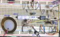
By way of explanation, this is why you do not use pictures of the components when diagramming electronics:


Each and every one of these devices, if substituted for one of the others in a circuit, would at best result in a non-functional circuit. At worst, they would fry themselves and/or the circuit they're installed in.
 

ScottWang

Joined Aug 23, 2012
7,400
The below is the circuit that I tested ok with 5V power and I used the piezo elements as your linked video, and that circuit is the same with Doktor Jones suggested on #19, so I didn't draw some more, and the input values of resistor is different, this will be causing the amplitude of op amp is different.

I didn't follow the circuit of Doktor Jones suggested to try, it just happened in the same time when I completed the testing and then I found he linked the page is the same as what I tried.

Every piezo element has different characteristic, so when you want to try it, you have to adjust the resistor to suit what you need.


Attachments

Last edited:

Thread Starter

Joey.Jerry

Joined Jun 8, 2014
53
Hello ScottWang,
I've done a breadboard pictograph of the circuit you've given me.Is that right?Or should I make any changes?( PS-I didnt get the right IC's image in the breadboard.)
Tell me your opinion.
 

Attachments

ScottWang

Joined Aug 23, 2012
7,400
Hello ScottWang,
I've done a breadboard pictograph of the circuit you've given me.Is that right?Or should I make any changes?( PS-I didnt get the right IC's image in the breadboard.)
Tell me your opinion.
For a LM358 op amp, the pin 8 is the power pin, so it should be connecting to +V, and the pin 4 should be connecting to GND.

The Pin 1 is the output, normally you can't connecting to the +V area, you should connecting to another position where you chose.

The piezo and two resistors 220Ω and 100K are on the right positions.

You can google LM358 and choosing the image mode to see the pin arrangement.
 

Thread Starter

Joey.Jerry

Joined Jun 8, 2014
53
For a LM358 op amp, the pin 8 is the power pin, so it should be connecting to +V, and the pin 4 should be connecting to GND.

The Pin 1 is the output, normally you can't connecting to the +V area, you should connecting to another position where you chose.

The piezo and two resistors 220Ω and 100K are on the right positions.

You can google LM358 and choosing the image mode to see the pin arrangement.
I tied it according to the schematics provided by you. But at some point it went wrong for me :(
 

ScottWang

Joined Aug 23, 2012
7,400
Long long time ago, I was thought that I want to make a electonics drum, it is make by bjt RC shift phase circuits and the white noise circuits, the contacts that I thought was used micro switches and potential meter, and some small spring, the thought only in my mind, because i'm not satisfy for the input methods, so I didn't do it.

During these day, I was reverse to used the piezo buz, that is a output component, but I used it as an input component, the method similar as using a speaker as a microphone, because months ago that I just bought some different types of piezo buzs(And I already destroied one), so that's why I can try the circuit.

In the beginning that I was tried to use NE555, but it needs a inverter, so it need 3 parts as 2SK30,NE555 and bjt, so I decided to used the 2SK30 and bjt to tried, and it worked, after that you mentioned that you went to use op amp as 741, so I decided to used the LM324(I got a lots of LM324) to try, and abandoned the 2SK30, because the 2SK30 was a component for amplifying here, when I changed to used an op amp and then the 2SK30 was no need any more.
 

Thread Starter

Joey.Jerry

Joined Jun 8, 2014
53
If you really did a experiment then attach your breadboard, describe what's the problems and more details.
I didnt experiment it because none of these components are available locally near me :( .So before i buy anything online with a high shipping rate,it should be sure that the circuits that i'm making is exactly perfect. Do you have a video or images of this circuit you've made?
 

absf

Joined Dec 29, 2010
1,968
Hello ScottWang,
I've done a breadboard pictograph of the circuit you've given me.Is that right?Or should I make any changes?( PS-I didnt get the right IC's image in the breadboard.)
Tell me your opinion.
The layout of the LM358 on the breadboard is completely fouled.

The way you inserted the chip, pin 1 is shorted to pin 8, 2-7, 3-6 and 4-5. Imagine you V+ is on pin 8, your output of the op-amp is directly connected to V+.

Besides, the V+ should go to Pin 8 not Pin 1. The black wire should go to pin 4 not pin 3.

Shift the LM358 down by 3 holes and it'll be OK.


Allen
 

Attachments

Last edited:

Thread Starter

Joey.Jerry

Joined Jun 8, 2014
53
Long long time ago, I was thought that I want to make a electonics drum, it is make by bjt RC shift phase circuits and the white noise circuits, the contacts that I thought was used micro switches and potential meter, and some small spring, the thought only in my mind, because i'm not satisfy for the input methods, so I didn't do it.

During these day, I was reverse to used the piezo buz, that is a output component, but I used it as an input component, the method similar as using a speaker as a microphone, because months ago that I just bought some different types of piezo buzs(And I already destroied one), so that's why I can try the circuit.

In the beginning that I was tried to use NE555, but it needs a inverter, so it need 3 parts as 2SK30,NE555 and bjt, so I decided to used the 2SK30 and bjt to tried, and it worked, after that you mentioned that you went to use op amp as 741, so I decided to used the LM324(I got a lots of LM324) to try, and abandoned the 2SK30, because the 2SK30 was a component for amplifying here, when I changed to used an op amp and then the 2SK30 was no need any more.
Hey,
Dont give up :p
Make a drum kit. You can have fun(atleast). Also,it would be a helpful work for me as well.
Try it man. :). Did you ever tried to use an arduino mega or an arduino with incresed inputs to make a kit?(I dind't)
 

ScottWang

Joined Aug 23, 2012
7,400
I didnt experiment it because none of these components are available locally near me :( .So before i buy anything online with a high shipping rate,it should be sure that the circuits that i'm making is exactly perfect. Do you have a video or images of this circuit you've made?
Although my experiment was successful, but it didn't means that you will be success, it just had a target to comparing to, that's all.

The below is my breadboard to do the experiment about piezo trigger, the Piezo buz has a Alligator Clip to connecting to the 220Ω, I was used 4,5,6 pins, and don't care the pins with circuit, they just another set of LM324, the 2SK30 and NE555 also on the breadboard.


Attachments

ScottWang

Joined Aug 23, 2012
7,400
The LED2 was on the circuit, and also don't care the bjt 2SC1384, I just to get what I can get and it is ok to try, and the LED1 was I added to indicating the output voltage of LM324.
 

Thread Starter

Joey.Jerry

Joined Jun 8, 2014
53
The LED2 was on the circuit, and also don't care the bjt 2SC1384, I just to get what I can get and it is ok to try, and the LED1 was I added to indicating the output voltage of LM324.
Hello ScottWang,
I've done it again. Please check and tell me if its right or wrong. Also do we need to provide power supply to this circuit and then will it go to the pc keyboard's keys?Do we need to provide power supply to each piezo we use?

Thanks.
 

Attachments

Top