Can you please add a schematics which include the circuit to add the power supply to pin4 and pin 11 as you told??I didnt do it because it was not there in the previous schematics.Please help.
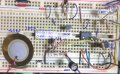
I only have the cellphone to get online, i can't draw the new circuit until i back to Taipei, but you can trying to figure out that i will tell you the LM324 on the breadboard at #38, i was rotate the normal LM324 180 degrees clockwise, so the pin 14 was the rightest of the bottom, and the pin 7 was the leftest of the top.
Hey ScottWang,
I cant understand your breadboard connection. And thanks for the diagram,but I'm weak in electronics. You've shown me the diagram as two different ones,So,what I actually want is a single schematics which has both the connections(the LM324 +ve & -ve and the basic circuit schematics for piezo) in it. Only then I can understand.Please help.
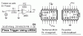
The LM324 has 4 sets of op amps, you can choose any one of them, and connecting the power of LM324 as the pin diagram, you can also choose the left one or the right.
you have to identify the mark of LM324 first, that is a very important thing to do, if the mark of concave is on the left side, that is the normal or standard way and you can see the mark of IC number is the positive, the right one was for the breadboard, i rotate the LM324 around 180 degrees clockwise, that is to match the +Vcc and GND of breadboard, because the +Vcc of breadboard is on the up side, and GND is bottom, this is pretty normal, but the +Vcc of LM324 is on the bottom, and the -Vee is on the up side, so I decided to rotate it around.
But can you please draw a complete diagram including connecting the + & - terminals also??
Also,can we use a 741 op amp instead of LM324??,because I guess it will require low power supply as considered to lm324.Please give the completely understandible diagram.
Thanks.
But can you please draw a complete diagram including connecting the + & - terminals also??
Also,can we use a 741 op amp instead of LM324??,because I guess it will require low power supply as considered to lm324.Please give the completely understandible diagram.
Thanks.
That is the simplest way to do, you just follow the circuit and connecting the +Vcc and GND, that's all.
Because you have many inputs, so using the LM324 is better, it has Wide Power Supply Range: 3V~32V (or±1.5~16V), and using it could be reducing the PCB size and IC quantities.
Ok,I'll connect the 4th terminal to +ve and 11th terminal to negative current.But I have a doubt, to where should I connect the Vo and the ground wires in the main circuit??Suppose to test the circuit,to light an LED,Should they(Vo and the ground wires in the main circuit) go directly into the LED ??? And Can we connect 4 piezo triggers to a single LM324?Also,how much voltage of current should supply to power the LM324??
Ok,I'll connect the 4th terminal to +ve and 11th terminal to negative current.But I have a doubt, to where should I connect the Vo and the ground wires in the main circuit??Suppose to test the circuit,to light an LED,Should they(Vo and the ground wires in the main circuit) go directly into the LED ??? And Can we connect 4 piezo triggers to a single LM324?Also,how much voltage of current should supply to power the LM324??
The +Vcc was provided from the Power, the voltages are +5V or 9V / 100mA or higher..
The +Vcc only connecting to the pin 4 of op amp from power, and the GND of power should be connecting to the pin 11 of the op amp, and the circuit has ground symbol.
Hey,Thank you for this. But can you tell me what are the resistance values of R3,R6,R9,R12???? Do they all have the same value and what is the resistance???I'm using a 9V battery currently for testing.Is that OK?
Hey,Thank you for this. But can you tell me what are the resistance values of R3,R6,R9,R12???? Do they all have the same value and what is the resistance???I'm using a 9V battery currently for testing.Is that OK?
I already offer two values of resistors for the LED, the values of R3, R6, R9, R12 as following:
Power : +5Vcc, 120Ω for 3V/20mA/5mm LED, 5mm is the diameter of LED.
Power : +5Vcc, 180Ω for 2V/20mA/5mm LED, 5mm is the diameter of LED.
power : +9Vcc, 360Ω for 3V/20mA/5mm LED, 5mm is the diameter of LED.
power : +9Vcc, 430Ω for 2V/20mA/5mm LED, 5mm is the diameter of LED.
The 2V LED is normal light, the 3V LED is high high.
It seems that you didn't read the LM324 datasheet, since you need to use the LM324, then you have to read it carefully and post the questions, so much information in the datasheet you should read it.
Ok,but the LEds are just for representation of a circuit. And i hope that you know I want to use these piezo triggers as keys of a keyboard to trigger drum sounds through a software!
Ok,but the LEds are just for representation of a circuit. And i hope that you know I want to use these piezo triggers as keys of a keyboard to trigger drum sounds through a software!
Although the LEDs just the indicators, but if using the wrong limiting resistors will get the wrong messages, or even burn the LEDs.
The output of op amp provide a transient voltage according to the pressure of peizo, if you want to using the voltage as a key trigger, you can't use the peizo directly, because the voltage of peizo may not enough.
But I have a doubt, Here in the circuit we are just connecting the LED directly to the Lm324's pins.But the keyboard's key wires have current passing through them. Is that a problem?Because we're connecting power supply via 4th and 11th pins of lm324 and when it is connected to a PC keybaord,power supply will come in that way also.What do you say?
If you using the op amp to amplifying the signal of piezo, the output of op amp only can be use them independently, you can't use them as dot matrix key to input.
If you want to using the dot matrix key to input, I have to thinking over.
 Facebook
 Google
 GitHub
 Linkedin