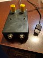
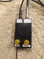
Alright, so I built this circuit but it's not functioning . The only change I made from the schematic in post 5 is there's a 100k pot for pulse width where it calls for a 10k pot. I've gone over the circuit many times and believe I have all the wiring correct.
As soon as I hook power up I cannot get voltage anywhere across the circuit (including the USB wires themselves) . If I hook up the 5v rail only and meter between the circuit at various points and the ground wire coming from the wall I get 5v in many places.
I have continuity all the way through my circuit, what could I be missing? What could I have done wrong?
I figured out my issue, I had a short due to a solder blob I didn't realize ended up ender my project board. It's working perfectly now . Thanks for all the help guys .
Hey, another quick question for ya . I built a second circuit and have gone over it extensively , it's identical to the first one. However this one isn't functioning correctly . When I power it up it sends pulses through the output jack over and over even with nothing plugged in to the input jack. It's a consistent pulse too, it's not intermittent .Also, when I turn the pulse width pot all the way to the left the pulse stutters a bit every time before going solid. Again on and off consistently every second or so .
Do I have a bad component? Perhaps a bad timer IC ? I'm totally stumped on this one.
Sounds like you may have some oscillations coming out of the LM386. You did connect the .1uf cap and 10 ohm resistor from pin5 to ground correct? Do you have an o- scope to look at the output?
SG
Sounds like you may have some oscillations coming out of the LM386. You did connect the .1uf cap and 10 ohm resistor from pin5 to ground correct? Do you have an o- scope to look at the output?
SG
I don't have an o scope, just a multimeter . The cap and 10ohm resistor look good and the connections look good too. Is it possible one of those is bad? Or should I try to swap out the 386?
I don't have an o scope, just a multimeter . The cap and 10ohm resistor look good and the connections look good too. Is it possible one of those is bad? Or should I try to swap out the 386?
I checked the voltage on pin 5 of the lm386. I'm getting a consistent 2.53volts (USB powered) unless I turn the pulse width pot all the way counterclockwise, then the voltage bounces between 2.51 and 2.52. I can't imagine that's a problem?
I checked the voltage on pin 5 of the lm386. I'm getting a consistent 2.53volts (USB powered) unless I turn the pulse width pot all the way counterclockwise, then the voltage bounces between 2.51 and 2.52. I can't imagine that's a problem?
OK. The next step is to disconnect the output of the amp from the 555 and connect a 100K resistor from pin2 of the 555 to 5 vdc. This will isolate the two circuits. Then see what happens.
SG
OK. The next step is to disconnect the output of the amp from the 555 and connect a 100K resistor from pin2 of the 555 to 5 vdc. This will isolate the two circuits. Then see what happens.
SG
The voltage on pins 6 and 7 only show .09 with the pulse width pot all the way counterclockwise, if I turn it slightly clockwise the voltage drops to 0 . Could it be a bad pot? The pot reads 87k resistance at both ends when turned away from it's outside pole .
Those voltages all appear correct and I'm sure it's not the pot. If it is still pulsing I would have to replace the 555. Might want to install sockets for the chips. I would also make sure the chips are genuine. There are a lot of bad copies out there.
SG
How would I test the chips? Is it possible I'm damaging them by overheating them when connecting them to my board? I don't think I'm overheating them, im going quick I believe .
I've made another circuit from all new parts and this one is not working either. I'm getting .6 volts at pin 5 of the 386 as opposed to the 2.5v it should and theres a constant voltage coming from pin 3 of the 555 to the transistor resulting in the output jack just staying in the closed state and sending a constant signal.
The 555s I got off Amazon and it was even the "recommended by Amazon" option, it's a Texas Instruments chip. The 386 I got from eBay and there's no telling about those being genuine. Is there a website you would recommend for the IC chips?
That's why I recommend using sockets for the chips.
The low voltage on pin5 of the 386 is causing pin3 of the 555 to stay high. In this case it's the 386 circuit causing the problem. Sounds like a bad chip or possible short on pin5.
I buy all my IC components from Digikey.
SG

 Facebook
 Google
 GitHub
 Linkedin


 Glad you got it working.




