Facebook
 Google
 GitHub
 Linkedin
https://imgur.com/a/yCI0j

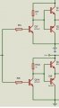
I found this inverter circuit online
I can't read it , can you explain it to me
thanks
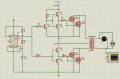
I found this inverter circuit online
I can't read it , can you explain it to me
thanks
Attachments
-
 188.7 KB Views: 25