Facebook
 Google
 GitHub
 Linkedin
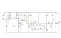
This is the schematic and the pcb version which is a bit different but overall the same thing
I built the exact same pcb years ago
I literally printed this pcb
And the circuit worked perfectly
It was there in my basement and I forgot to cover the pcb with a layer of epoxy or something to prevent the pcb from rusting or corrosion
Last week I tried to run it and it didn't work
So I desoldered all components, tested them with my multimeter, all were ok
I bought new ICs
Made the exact same circuit but now it doesn't work
There's not even a click at the speaker
I realized the circuit now draws 2.5amps at 11.5v
The coil is fed with DC voltage rather than AC
Tested all transistors and the mosfet off the circuit, they were ok but I replaced them
It just doesn't work
Draws 2.5 DCamps constantly
And no the coil is not shorted
My multimeter shows 2 Ohms across the coil off the circuit which is what it should be
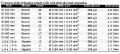
Attachments
-
 33.4 KB Views: 44
 -
 134.1 KB Views: 40