What keeps the RF signal stable in an RF amplifier?

Thread Starter

dante_clericuzzio

Joined Mar 28, 2016
246
I made quite a good RF amplifier but how is it possible the signal is being good overnight and then in the day comeback to worst...and then starting from there its become just ordinary again..

The whole night long was 4 bars...then in the day back to 2 bars and then new night come fluctuate within 2 ~ 3 bars. Am i missing something to stabilize the RF signal...I am in dire need of some ideas where i can research on

By the way its powered by 5 Volt USB is the amount of voltage instability can affect the signal strength? and without the amplifier it will be around 1 ~ 2 bar fluctuation
 

Papabravo

Joined Feb 24, 2006
22,084
I don't think your amplifier has anything to do with the bars you are seeing on your cellphone. Making an RF amplifier for cellphone frequencies is not a trivial task. Show us the schematic of this device.
 

Papabravo

Joined Feb 24, 2006
22,084
I follow this schematic
OK -- that's a start. Berfore analyzing the amplifier circuit, tell me how the antenna is connected to "inp" and how "out" is connected to the device measuring signal strength.

The bias current network for Q1 draws ≈ 4.5 mA, and Q1 in full conduction draws ≈ 18.5 mA. Q2 in ful conduction draws ≈ 95 mA. Here in lies your problem. A USB device is only required to provide 100 mA unless you negotiate with it for more. I don't see that you amplifier has any ability to negotiate with a USB master for more power. When the current draw exceeds 100 mA it may drop the +5V to a lower value.

BTW -- how come there are no emitter bypass capacitors on the 220 Ω and 2.2 Ω resistors?
 
Last edited:

Thread Starter

dante_clericuzzio

Joined Mar 28, 2016
246
OK -- that's a start. Berfore analyzing the amplifier circuit, tell me how the antenna is connected to "inp" and how "out" is connected to the device measuring signal strength.

The bias current network for Q1 draws ≈ 4.5 mA, and Q1 in full conduction draws ≈ 18.5 mA. Q2 in ful conduction draws ≈ 95 mA. Here in lies your problem. A USB device is only required to provide 100 mA unless you negotiate with it for more. I don't see that you amplifier has any ability to negotiate with a USB master for more power. When the current draw exceeds 100 mA it may drop the +5V to a lower value.

BTW -- how come there are no emitter bypass capacitors on the 220 Ω and 2.2 Ω resistors?
How much capacitance is appropriate on the bypass and why?
 

Motanache

Joined Mar 2, 2015
652
I wonder how this schematic still works.
Show me, please, how you use it that I want to learn something new.
I guess you have a RTL-SDR stick that does not have a good reception. Right?

How did you observed that this schematic creates the desired amplification?
 

nsaspook

Joined Aug 27, 2009
16,374
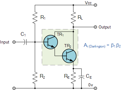
It looks like a common Darlington pair circuit used to increase input impedance. You don't bypass the 220 ohm resistor and maybe not the 2.2 ohm as it provides an amount of negative feedback for I would guess stability.


Thread Starter

dante_clericuzzio

Joined Mar 28, 2016
246
I wonder how this schematic still works.
Show me, please, how you use it that I want to learn something new.
I guess you have a RTL-SDR stick that does not have a good reception. Right?

How did you observed that this schematic creates the desired amplification?
Well this is what i did -- I use a crystal oscillator 20 Mhz push the signal to a small inductor and pass to another inductor the frequency will increase up to 800 Mhz to 1 Ghz and then amplify then goes through a coaxial 50 Ohm impedance and then amplify using the above circuit diagram then output to another coaxial 50 ohm which direct goes into the 4G wifi modem..i have a mini frequency counter that can measure signal up to 1.5 Ghz..This thing really works usually my indoor signal is about 1 to 2 Bars using this around 3 to 4 bars but not consistent where in the day the signal will reduce and in the night will goes up much better

3 Things i want to improve on this circuit -- increase the signal bar to maximum 5, Maintain greater stability to the signal, and make the antenna able to capture the slightest of signal from the surrounding even a tiny signal need to be harvested into the input antenna..

The 4G wifi modem looks like this

 
Last edited:

Papabravo

Joined Feb 24, 2006
22,084
Well this is what i did -- I use a crystal oscillator 20 Mhz push the signal to a small inductor and pass to another inductor the frequency will increase up to 800 Mhz to 1 Ghz and then amplify then goes through a coaxial 50 Ohm impedance and then amplify using the above circuit diagram then output to another coaxial 50 ohm which direct goes into the 4G wifi modem..i have a mini frequency counter that can measure signal up to 1.5 Ghz..This thing really works usually my indoor signal is about 1 to 2 Bars using this around 3 to 4 bars but not consistent where in the day the signal will reduce and in the night will goes up much better

3 Things i want to improve on this circuit -- increase the signal bar to maximum 5, Maintain greater stability to the signal, and make the antenna able to capture the slightest of signal from the surrounding even a tiny signal need to be harvested into the input antenna..

...
Well now I am even more confused than I was before. You have:
  1. An incoming signal from a cell tower in the 800 MHz. to 1 GHz range
  2. A 20 MHz. Oscillator
  3. Some "magic" frequency multiplier consisting of "a small inductor and pass to another inductor".
  4. "then amplify then goes through a coaxial 50 Ohm impedance and then amplify using the above circuit diagram"
  5. "to another coaxial 50 Ohm which direct goes into the 4G wifi modem"
I not sure I even think I know what you are doing. WiFi and cellphone signals do not use the same frequency bands.
Did it ever occur to you that cell towers may adjust their RF output as a function of the time of day?
Did it ever occur to you that a strong, out of band, RF source can overload the RF input of the WiFi modem and give you nonsense readings?
 

Thread Starter

dante_clericuzzio

Joined Mar 28, 2016
246
I not sure I even think I know what you are doing. WiFi and cellphone signals do not use the same frequency bands.
Did it ever occur to you that cell towers may adjust their RF output as a function of the time of day?
Did it ever occur to you that a strong, out of band, RF source can overload the RF input of the WiFi modem and give you nonsense readings?

I not sure I even think I know what you are doing. WiFi and cellphone signals do not use the same frequency bands. --- WiFi actually is not involve here although i mentioned its just that Wifi is part of the modem capability -- its just cell signal 4G which the modem received and use the internet from it

Did it ever occur to you that cell towers may adjust their RF output as a function of the time of day? -- This i don't know for sure...but it seems during the day the signal would be much slower and less

Did it ever occur to you that a strong, out of band, RF source can overload the RF input of the WiFi modem and give you nonsense readings? I don't think so. Without the amplifier my internet would be piece of crap almost unusable
 

Papabravo

Joined Feb 24, 2006
22,084
I not sure I even think I know what you are doing. WiFi and cellphone signals do not use the same frequency bands. --- WiFi actually is not involve here although i mentioned its just that Wifi is part of the modem capability -- its just cell signal 4G which the modem received and use the internet from it

Did it ever occur to you that cell towers may adjust their RF output as a function of the time of day? -- This i don't know for sure...but it seems during the day the signal would be much slower and less

Did it ever occur to you that a strong, out of band, RF source can overload the RF input of the WiFi modem and give you nonsense readings? I don't think so. Without the amplifier my internet would be piece of crap almost unusable
I obviously do not have a clear picture of what you are trying to do. You do realize that your connection to the cellphone system has to work both ways. If you insert an amplifier in the receive path, for example, then you might also need an amplifier for the transmit path. I think it is more likely you will need an amplifier for the transmit path than the receive path. Receivers are just so damn sensitive and selective that they can pick signals out of the mud. The phone companies can run high power transmitters easier and cheaper than you can. The weak link in consumer cellular devices is the low power transmitter in the hand held device running off of a battery.
 

Thread Starter

dante_clericuzzio

Joined Mar 28, 2016
246
I obviously do not have a clear picture of what you are trying to do. You do realize that your connection to the cellphone system has to work both ways. If you insert an amplifier in the receive path, for example, then you might also need an amplifier for the transmit path. I think it is more likely you will need an amplifier for the transmit path than the receive path. Receivers are just so damn sensitive and selective that they can pick signals out of the mud. The phone companies can run high power transmitters easier and cheaper than you can. The weak link in consumer cellular devices is the low power transmitter in the hand held device running off of a battery.
The goal is only one to make better signal for my modem and get good internet..

So far with the amplifier the internet is better it's just that probably I am asking too much to get the maximum 5 bars and consistently. I will stick with whatever i have for now since all is good.

BTW the signal without amplification is around 1 to 2 bar and this is confirmed by my cellphone signal without any amplification. Never it goes up to 3 or 4. So I am pretty sure it works very well.
 
Last edited:

Papabravo

Joined Feb 24, 2006
22,084
The goal is only one to make better signal for my modem and get good internet..

So far with the amplifier the internet is better it's just that probably I am asking too much to get the maximum 5 bars and consistently. I will stick with whatever i have for now since all is good.

BTW the signal without amplification is around 1 to 2 bar and this is confirmed by my cellphone signal without any amplification. Never it goes up to 3 or 4. So I am pretty sure it works very well.
Like I said this amplifier is on your receiver input. I doubt that your problem is with your receiver. It is more likely that the cell tower cannot hear your transmitter.
 

BR-549

Joined Sep 22, 2013
4,928
Are you trying to amplify a wifi signal or a cellphone signal?

Are your having problems with the cellphone to cell tower connection? Or is it the cellphone to modem connection using a wifi enabled cellphone? Which way are you trying to get the signal to go? Where is your ISP entering the system?

Do you notice any difference in quality when signal goes above 2 bars?
 

Thread Starter

dante_clericuzzio

Joined Mar 28, 2016
246
Are you trying to amplify a wifi signal or a cellphone signal?

Are your having problems with the cellphone to cell tower connection? Or is it the cellphone to modem connection using a wifi enabled cellphone? Which way are you trying to get the signal to go? Where is your ISP entering the system?

Do you notice any difference in quality when signal goes above 2 bars?
1. I am trying to amplify cellphone signal (my internet using 4G LTE signal)
2. I am having problem of my 4G modem signal around 1 to 2 bars
3. Yes at 1 to 2 is quite slow around 2 ~ 3 Mbps and around 3 to 4 is 5 ~ 10 Mbps
 
Top