What is the Real AC Voltage Phase Shift Across A Capacitor??

What is the Voltage Phase Shift Across A Capacitor in a series RC Circuit with AC Power.

  • 180 Degrees

    Votes: 1 16.7%
  • 90 Degrees

    Votes: 4 66.7%
  • Depends on Measurment Reference Point

    Votes: 0 0.0%
  • Depends on My Specific Formula (Relative to Power Source Ground Ref)

    Votes: 1 16.7%
  • Depends on the exact AC Waveform (sinus, square, sawtooth, etc.)

    Votes: 0 0.0%
  • All of the Above

    Votes: 0 0.0%
  • None of the Above

    Votes: 0 0.0%
  • Don't Know, Don't Care

    Votes: 0 0.0%

  • Total voters
    6

Jony130

Joined Feb 17, 2009
5,598
As further proof, i show in this simple simulation demonstration that the battery can also be viewed as a differential source, ie not a single ended output but a balanced differential output
But everyone knows that. But you "get" this "differential source" because you decided to choose your reference point (GND) somewhere between 0 to 10V . So you get this "differential source" only because the way you are measure it and where your reference point is placed. This is not the internal property of a battery or a capacitor. But I'm sure you already know this very well and you are only playing with us.

And this exampel shows how reference point (GND) change the voltage reading.
http://forum.allaboutcircuits.com/attachments/32-jpg.96573/
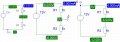
rys3.JPG
 
Last edited:

nsaspook

Joined Aug 27, 2009
16,429
But everyone knows that. But you "get" this "differential source" because you decided to choose your reference point (GND) somewhere between 0 to 10V . So you get this "differential source" only because the way you are measure it and where your reference point is placed. This is not the internal property of a battery or a capacitor. But I'm sure you already know this very well and you are only playing with us.
I hope so.
 

MrAl

Joined Jun 17, 2014
13,761
Hi,

We must not be understanding each other (Jony, nsas).
You guys cant get past the fact that in circuit analysis we can pick the 0v point and nobody on earth can say we are wrong.

A battery might be a good example, like a car battery, which everybody knows it made up of several cells in series.

What you guys seem to want to do is force everyone to pick the 0v point based on what you believe to be true, and im not even sure what that is at this point.

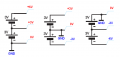
I showed three diagrams, the last one the most interesting because the two sides of the battery are +5 and -5, and that is the result of the SIMULATION. What the heck else could you possibly want?
Even the ones with the two resistors. Ground is half way between +5 and-5 and there is no other possibility with two equal value resistors.

But Jony, you are stating basically the same thing i am stating yet you are somehow implying that what i stated is wrong :)
That just doesnt make sense.

I said: "We can pick the 0v point anywhere we want to".
You said: "But you are picking the 0v point wherever you want it to be".

My reply then would have to be, "Yes, that's what we are allowed to do in circuit analysis". Read up on it. The 0v point is arbitrary and is the choice of the person doing the analysis. If that person wants it to be on Mars then that's what they choose. You are free to pick another place, but all the calculations come out right in either case.

In any argument so far i have not seen any evidence of any Law of circuit theory being broken except for the insistence that the 0v point is somehow universally chosen when it is really arbitrary.
 
Last edited:

nsaspook

Joined Aug 27, 2009
16,429
Hi,

I showed three diagrams, the last one the most interesting because the two sides of the battery are +5 and -5, and that is the result of the SIMULATION. What the heck else could you possibly want?
Now I know for sure you are joking.
 

MrAl

Joined Jun 17, 2014
13,761
Now I know for sure you are joking.

Hi,

And i believe you.

Now maybe you can get back to your proof rather than just blurt out subtle mockery. I believe you are better than that.

But in the end if you want to call some point 0v and try to stop someone else from calling it at a different point, that's entirely up to you. Have fun with it :)
 

nsaspook

Joined Aug 27, 2009
16,429
Hi,

And i believe you.

Now maybe you can get back to your proof rather than just blurt out subtle mockery. I believe you are better than that.

But in the end if you want to call some point 0v and try to stop someone else from calling it at a different point, that's entirely up to you. Have fun with it :)
 

MrAl

Joined Jun 17, 2014
13,761
Hi,

Hey, that's cute. I had a feeling you were a little girl but now that you've submitted the proof i am sure (he he just kidding of course) :)

Where the heck are you finding this stuff?
I just wonder what you have to do a search for to find stuff like that :)

Thanks for adding a little humor here. I love comedy almost as much as electronics.
 

Jony130

Joined Feb 17, 2009
5,598
But Jony, you are stating basically the same thing i am stating yet you are somehow implying that what i stated is wrong :)
I said: "We can pick the 0v point anywhere we want to".
You said: "But you are picking the 0v point wherever you want it to be"
Yes, this is true that we can pick a 0V point anywhere we want to. But this point must be located on the circuit (you can pick any node).
And I'm OK with that.

My problem is that it seems to me that you convince the TS that the capacitor is responsible for this 180d phase shift. Not the reference point. But a capacitor neither knows or cares what or where our reference point is located. All it knows are the voltage differences between its terminals and the currents that is flowing through it.
I showed three diagrams, the last one the most interesting because the two sides of the battery are +5 and -5, and that is the result of the SIMULATION. What the heck else could you possibly want?
For me this is a typical exampel of a GIGO. As you now any real world voltmeter need a "closed loop" to be able to measure any voltage.
And in your example (3) we have electrically disconnected points. So any real world voltmeter will measured a zero voltage difference.
 

nsaspook

Joined Aug 27, 2009
16,429
"Ground exists only in the mind of the person analyzing the circuit". Circuit Common is usually a better word for that point. The electrical meaning of "Earth" should be distinct from circuit ground.

Part of the discussion here is the difference between a zero reference and zero volts during a relative measurement or some bogus simulation.

Example:
If you have a meter in a circuit across a 1000Ω resistor with a positive series current of 5mA you would expect the reading to be +5 volts (Potential Difference) across the resistor if the negative meter lead is connected to the negative potential IRT the resistor and the positive meter lead was connected to the other end of the resistor. Now if the meter has a REL Δ function like the Fluke 87 (or REL SET on my 2465A DM) you can use that to make the current voltage reading a zero reference.
(Relative mode) Stores the present reading as a reference for subsequent readings. The display is zeroed, and the stored reading is subtracted from all subsequent readings.
With this meter setting and connections if I reduce the current to zero in the resistor circuit by opening the circuit the meter now reads -5 volts because of the stored zero reference. Is the Potential Difference across the resistor actually -5 volts?
 

Thread Starter

ozsavran

Joined Jul 30, 2016
21
Dear Guys,

Thanks everybody for contributing so much to my timid little inquiry here with so rich information about measurement and circuit analysis. Seeing it grow like that I simplified/clarified thread title and added a poll for different opinions. If that poll section is annoying for majority, I will gladly remove it.

My lab experiments today could not prove my point, but were enjoyable. I shall continue attacking this issue until my point is at least visible. :)

Cheers!
 

Jony130

Joined Feb 17, 2009
5,598
My lab experiments today could not prove my point, but were enjoyable. I shall continue attacking this issue until my point is at least visible.
I think that You should start with this simple circuit and try to use two batteries in series and one voltmeter.
1x.png
1 - connect your black probe tip (at the bottom) the GND and use a read probe tip to measure the voltage at all of nodes (first case).
2 - now reconnect your black probe tip to the the middle node ( GND) and repeat the measurement using a read probe tip ( second case).
3 - the black probe tip connected to the top node ( GND ) and repeat the measurement using a read probe tip ( third case).

And the second case (black probe tip between two batteries) should give you a tip why you see this 180d phase shift in your AC circuit. Try in yourself at home.
http://forum.allaboutcircuits.com/threads/what-is-negative-voltage.119909/#post-954087
 

AnalogKid

Joined Aug 1, 2013
12,232
What you can say is that with respect to the point half way between the two plates of the capacitor the voltages on the capacitor plates are equal and opposite. And in an AC circuit their voltages with respect to that midpoint are 180 degrees apart.
Don't think so. Equal and opposite with respect to an arbitrary internal reference point is not the same as equal and opposite in the outside world. Also, while "opposite phase" is defined as 180 degrees in balanced audio, that is not automatically true everywhere else in this universe. (Standard disclaimer: these conditions do not necessarily apply on Mars.)

If an AC circuit voltage phase shift across a capacitor is 90 degrees, then, with respect to an arbitrary and invisible half way point inside the cap, the two plates are each 45 degrees shifted (one leading and one lagging) so the sum is 90 degrees. If the outside phase shift is 60 degrees, as in a traditional phase shift oscillator circuit, the two series inside phase shifts in each cap would be 30 degrees each about the invisible center point. A common source of confusion is trying to visualize this as it would appear on a scope. Nope. A scope uses Cartesian coordinates, while phase algebra uses polar coordinates. In NTSC video, the tint information is carried as the phase angle of a constant frequency sinewave when compared to a short burst of a reference wave. To view this, Tektronix developed the vectorscope. Instead of sweeping left to right, it scans in a circle and shows amplitude as a function of phase angle instead of as a function of time.

In post #1 the TS confuses voltages with respect to an internal reference point, with external voltages measured with respect to something (anything) else. After 20 posts, the two still are not the same.

ak
 

DGElder

Joined Apr 3, 2016
351
DGElder said:
What you can say is that with respect to the point half way between the two plates of the capacitor the voltages on the capacitor plates are equal and opposite. And in an AC circuit their voltages with respect to that midpoint are 180 degrees apart.

Analogkid said: "Equal and opposite with respect to an arbitrary internal reference point is not the same as equal and opposite in the outside world."


I never said it was the same. Did you read the rest of my post/s?
 
Last edited:

MrAl

Joined Jun 17, 2014
13,761
One question here... if a 0V point of reference can be defined anywhere, then what is ground supposed to be?
Hi,

Ground is a little difference than 0v. Ground can be defined by the circuit designer while 0v can be chosen by the circuit analyst.
If the circuit analyst chooses to conform to the designers choice of 0v also, then they may do so, or not.
 

MrAl

Joined Jun 17, 2014
13,761
Yes, this is true that we can pick a 0V point anywhere we want to. But this point must be located on the circuit (you can pick any node).
And I'm OK with that.

My problem is that it seems to me that you convince the TS that the capacitor is responsible for this 180d phase shift. Not the reference point. But a capacitor neither knows or cares what or where our reference point is located. All it knows are the voltage differences between its terminals and the currents that is flowing through it.

For me this is a typical exampel of a GIGO. As you now any real world voltmeter need a "closed loop" to be able to measure any voltage.
And in your example (3) we have electrically disconnected points. So any real world voltmeter will measured a zero voltage difference.
Hi,

I dont see how you come to these conclusions.

I showed that the same thing happens with a battery. That's not a capacitor.

You also need to understand the concept of a ground at infinity. You dont need a loop to test for voltage in theory.
 
Top