What is the Real AC Voltage Phase Shift Across A Capacitor??

What is the Voltage Phase Shift Across A Capacitor in a series RC Circuit with AC Power.

  • 180 Degrees

    Votes: 1 16.7%
  • 90 Degrees

    Votes: 4 66.7%
  • Depends on Measurment Reference Point

    Votes: 0 0.0%
  • Depends on My Specific Formula (Relative to Power Source Ground Ref)

    Votes: 1 16.7%
  • Depends on the exact AC Waveform (sinus, square, sawtooth, etc.)

    Votes: 0 0.0%
  • All of the Above

    Votes: 0 0.0%
  • None of the Above

    Votes: 0 0.0%
  • Don't Know, Don't Care

    Votes: 0 0.0%

  • Total voters
    6

MrAl

Joined Jun 17, 2014
13,751
Dear Guys,

Thanks everybody for contributing so much to my timid little inquiry here with so rich information about measurement and circuit analysis. Seeing it grow like that I simplified/clarified thread title and added a poll for different opinions. If that poll section is annoying for majority, I will gladly remove it.

My lab experiments today could not prove my point, but were enjoyable. I shall continue attacking this issue until my point is at least visible. :)

Cheers!
Hi,

What experiments?

This thread is just getting ridiculous. Some people just dont want to take the time to understand the basics of circuit analysis. When that happens, there's going to be no reasoning with them because they have too little theory behind them to form a reasonable argument.

Also, i have to unfortunately, mention that a poll of some kind could just confuse the issues even more than they are already. That's because if in any group you have 7 people that dont know what they are talking about and three that do, the 7 will vote randomly with respect to reality while the 3 will vote perfectly. Since the mean of 7 is 3.5, the random votes will determine the outcome of the poll, which in turn means it is a random outcome that has no bearing on reality. In other words, the people who dont know what they are talking about will determine the outcome, not the ones that actually know what is going on. See saw this in what many people believe has happened with Brexit...many uninformed people determining the outcome.

Personally i just see a bias here in this thread. Despite a ton of reasonable information certain key points are rejected without much consideration. Even a simulation does not help to sway the judgement of the biased...because they are looking for any excuse to reject it. Why they choose to do this i dont know and dont care now that i have seen the bias.

Also, there is nothing that can change basic circuit theory so there will never be a reasonable argument against the fact that we can choose the 0v point reference anywhere we choose in any analysis. Not a poll, not an experiment, nothing. It's a fact of the way we do things. When we choose different points we will see different outcomes, that's life.

Also, test probes come in many forms and so do capacitors. There have been experiments with fairly large capacitors done with fairly high voltages. In chose kinds we can actually probe the space inside the capacitor, between the plates.

I do have one last question though, how do we unsubscribe to a thread so we dont 'watch' it anymore :)

Seriously though, you guys argue about this all you want, keep it going for the next 10 years if you care too :)

I probably wont check back to this particular thread unless i hear of something drastically changing. I still look forward to many more intelligent discussions in other areas though.

One last comment:
The title of this thread does not match the intent of the question asked in the first post. The voltage phase shift 'across' a capacitor is usually based on the capacitor and the external impedance. So while the internal view is 180 degrees, the phase shift across the cap is based on the cap and the external impedance:
Vc=Vs*(1/sC)/(Z+1/sC)
PhaseAngle=atan2(r(Vc),i(Vc))
where
r(Vc) is the real part of Vc, and
i(Vc) is the imaginary part of Vc,
and of course Vc is the complex voltage across the capacitor.
 
Last edited:

nsaspook

Joined Aug 27, 2009
16,405
This thread is just getting ridiculous. Some people just dont want to take the time to understand the basics of circuit analysis. When that happens, there's going to be no reasoning with them because they have too little theory behind them to form a reasonable argument.
The problem I see with your analysis is a mixing of pure circuit theory (KVL/KCL) lumped elements with major constraints (simplifying assumptions) with a field based classical electrodynamics analysis of the internals of elements. This results in a water/oil mixture that's very confusing to a clear understanding of simple circuits for beginners because while the rational for a physics based understanding might be justified in terms of pure learning the mixing of domains creates a minefield for missteps.

What are the major circuit theory constraints?
https://en.wikipedia.org/wiki/Lumped_element_model#Lumped_matter_discipline
Lumped element model[edit]
The lumped element model of electronic circuits makes the simplifying assumption that the attributes of the circuit, resistance,capacitance, inductance, and gain, are concentrated into idealized electrical components; resistors, capacitors, and inductors, etc. joined by a network of perfectly conducting wires.
Now if you really want to violate the assumptions of lumped element circuit theory to probe internal capacitor fields then you need to stick to a classical EM based analysis like I would need to do calculate the deflections of accelerated charged particles passing through a set of electrostatic scanner plates.
https://sun.iwu.edu/~gspaldin/DeflectionByE-field.pdf
http://www.feynmanlectures.caltech.edu/II_29.html

 
Last edited:

MrAl

Joined Jun 17, 2014
13,751
This explains it.
Read what the University of Michigan has to say about the voltage inside a capacitor:
https://www.google.com/url?sa=t&rct=j&q=&esrc=s&source=web&cd=1&ved=0ahUKEwjsjJTW-KnOAhXD4CYKHXtFDTQQFggcMAA&url=http://www.physics.umd.edu/courses/Phys260/agashe/S08/notes/lecture34.pdf&usg=AFQjCNH5iqtiS8Ky_Yos-h_-Z5vEUSt6CQ&bvm=bv.128617741,d.eWE&cad=rja

Hello,

The problem i see with your analysis of my analysis is that it again comes to the wrong implied conclusion of my analysis, with included quotes of *possible* calculations without the actual calculations, which means there is still no proof.
Instead of quoting calculations that *may* lead to some other conclusion, go ahead and do some calculations and see what happens. If you dont come to the conclusion that we can find a zero reference *inside* the capacitor in which to base our measurements at the plates, then dont expect me to agree with it, ever.

Also, from the posts i read it appears that we are not dealing with a 'beginner' but an advanced thinker.

Also, you seem to want to place some sort of blame on me that there is some mix between assumptions about how the analysis should proceed. I was not the one who asked the question about the phase across a capacitor and then asked about the internal view of what is happening.
Also, i had said all along that there are different views of the situation, including the 90 degree current vs voltage phases.

But as you can see by now each party in a discussion needs to show proof if a question comes up where each side takes a different stance, and that proof has to be in a form that clearly displays the point of the author. I gave several examples and even did a simulation where we actually had numbers to look at. Ask why the simulation would show +5v and -5v for a 10 volt battery source. The only answer must be that the designers of the program knew something that you apparently do not agree with. So really you not only have to prove what ever it is you seek to show in the first place, you've also got to show that a pretty decent simulator is WRONG too.

I have a feeling this post isnt going to do any good either, but i figured i would give it one last shot :)

I do want to remind you though that you have the right to believe whatever you want to believe in a free country. If you want to believe that +5v and -5v is somehow the wrong result, that's entirely up to you. I can guarantee you though that you will never convince me that it is wrong. I actually learned about this back in the 1980's when it came into focus about how sources and capacitors behave in converter circuits, especially in switched capacitor circuits when the capacitor can actually be free floating for a finite time period simply because it is switched out of the circuit for a short time, and what happens to the external circuit once the capacitor is switched back in. That's very informative to look at.
This reminds me that it is helpful to look at circuits for this and other kinds of questions that come up now and then too.

To put it another way, a capacitor can easily be modeled by two capacitors in series here each one has part of the total value. It is a fact that no matter what values we choose for the two if we choose the central node as the reference point, then the outer two leads are of different polarities, plus and minus. The amplitudes may be different, but the polarities are always opposite.

You can use whatever method you choose, but whatever method you do choose the outcome has to be in the form of one or more voltages and some reference point.
 
Last edited:

nsaspook

Joined Aug 27, 2009
16,405
Instead of quoting calculations that *may* lead to some other conclusion, go ahead and do some calculations and see what happens. If you don't come to the conclusion that we can find a zero reference *inside* the capacitor in which to base our measurements at the plates, then don't expect me to agree with it, ever.
Made you reply.

I repeat that a zero reference that can be defined as anything and anywhere (even inside circuit elements when not using circuit theory constraints) is not the same as actual zero volts in circuit theory. There's nothing mysterious about a capacitor that you and anyone else discovered in the 80's.
 
Last edited:

atferrari

Joined Jan 6, 2004
5,019
Part of the discussion here is the difference between a zero reference and zero volts during a relative measurement or some bogus simulation.
Not qualifying myself to give an opinion, the above is what I felt since page 1. But, as usual, I may be dead wrong.

And so the plot thickens... this thread has my undivided attention
Mine too César, but please, stay close. I am lost already!!
 

Thread Starter

ozsavran

Joined Jul 30, 2016
21
Hi,

We do get the 180d phase shift effect when we divide either a capacitor or a resistor in half and take the middle point as measurement reference base. So that's just measurement direction effect. Even within slightly more advanced circuits icluding some diodes etc. I can put sims for all that in another message without comment.

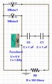
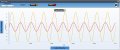
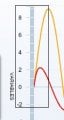
Now, if we please concentrate carefully at the third picture below, its half a cycle from source. Does anybody have a good electron charge movement based explanation as to why the bottom lead of the capacitor is also rising to positive potential relative to circuit ground, and then starts going down before the top lead voltage potential starts doing so please? No circuit analysis please. Only actual particle movement is what I am interested.

Capacitor-Circuit5-01.jpg Diode-03_Output-08.jpg Diode-03_Output-08-Part.jpg


A- Should we differentiate between the plates and leads of the capacitor? Should I make my own capacitor and measure potential on inside faces of the capacitor plates to understand what charge particles are doing exactly? I mean how can positive charges relative to earth ground be collecting on that plate despite repulsion from the other plate? If there are positive holes on one plate they should (supposed to) be attracting electrons on the other side, thereby making the other side negatively charged relative to neutral ground, isn't it? Appearantly not. But why?

B- In fact, what exactly happens on capacitor plates when the source is DC? If negative side of DC source is grounded along with lower plate of capacitor. Now upper plate is positively charged, lower plate supposed to attract electrons and negatively charged. But we do have to measure 0V there as its connected to reference ground. Again do we have to measure inside of the lower capacitor plate to see negative charge accumulation?

Sorry, but yes I am this stupid and this ignorant of theory. Where are those darned electrons exactly? :)
 
Last edited:

DGElder

Joined Apr 3, 2016
351
At the risk of beating a dead horse into a fine puree'.....

Mr. Al

You lost me a long time ago. Can you succinctly state your position and how you think it differs from mine, crutschow or nsaspooks? Please don't defend it, I just want to know what it is.

We seemed to be making some progress with the TP on the first page of the thread and then it seemed to me that you gave him an ambiguous theoretical fig leaf to hide behind and that got him to think he was correct all along and the "experts" disagreed on this point about the fundamentals of capacitors, charge and voltage. I don't see anywhere where you corrected him of his notion that the phase difference of the voltages on the two plates of a capacitor with respect to ground in an AC circuit are always 180 degrees apart. The fact that they are 180 degrees apart in an AC circuit with respect to the midpoint between the capacitors plates has never been contested here by me, nsaspook, you or anyone else as far as I can see. In any case that does not address the TP's continued central point of confusion. So I am not sure if you agree with his tenet or exactly what you are arguing.

Despite the TP disproving his own proposition with his own original circuit simulation which showed the phase difference as near zero degrees, not 180 degrees in his circuit, he endeavored to find a circuit simulation example which would show a 180 degrees phase difference. Of course showing such an example would not prove his point because you only need one case where it is not true to show it is not always true. It is only true if you short out the resistor in the AC series RC circuit.

Case in point:
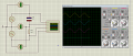
ozsavran said: "In my second circuit below, I made a 10V pp AC source by adding two 5V AC sources in series and putting earth ground between them. So there is no ground relative to anything, but just physical real earth ground. Simulation including both scopes and voltmeters show 2 sides of the capacitor at 180d voltage phase difference. It has to be."

upload_2016-8-5_14-15-3.png


In this AC RC simulation he shows near a 180 degree phase difference. But this is just the special case I mentioned above. Due to the low frequency (1 Hz) the impedance of the capacitor is 1000 time larger than the resistor, it's almost as if there is no resistor, i.e. the cap is just connected across the source so of course the plates are 180 degrees apart. You can see the entire voltage drop is across the capacitor (A-B) and practically zero across the resistor (B-C).

Anyway, increase the frequency of the source and the voltage phase difference (A vs B) of the capacitor plates will change. I trust we have no disagreement here?
 
Last edited:

Thread Starter

ozsavran

Joined Jul 30, 2016
21
At the risk of beating a dead horse into a fine puree'.....

Mr. Al

You lost me a long time ago. Can you succinctly state your position and how you think it differs from mine, crutschow or nsaspooks?

We seemed to be making some progress with the TP on the first page of the thread and then it seemed to me that you gave him an ambiguous theoretical fig leaf to hide behind and that got him to think he was correct all along and the "experts" disagreed on this point about the fundamentals of capacitors, charge and voltage. I don't see anywhere where you corrected him of his notion that the phase difference of the voltages on the two plates of a capacitor with respect to ground in an AC circuit are always 180 degrees apart. The fact that they are 180 degrees apart in an AC circuit with respect to the midpoint between the capacitors plates has never been contested here by me, nsaspook, you or anyone else as far as I can see. In any case that does not address the TP's continued central point of confusion. So I am not sure if you agree with his tenet or exactly what you are arguing.

Despite the TP disproving his own proposition with his own original circuit simulation which showed the phase difference as near zero degrees, not 180 degrees in his circuit, he endeavored to find a circuit simulation example which would show a 180 degrees phase difference. Of course showing such an example would not prove his point because you only need one case where it is not true to show it is not always true. It is only true if you short out the resistor in the AC series RC circuit.

Case in point:
ozsavran said: "In my second circuit below, I made a 10V pp AC source by adding two 5V AC sources in series and putting earth ground between them. So there is no ground relative to anything, but just physical real earth ground. Simulation including both scopes and voltmeters show 2 sides of the capacitor at 180d voltage phase difference. It has to be."

View attachment 109998


In this AC RC simulation he shows near a 180 degree phase difference. But this is just the special case I mentioned above. Due to the low frequency (1 Hz) the impedance of the capacitor is 1000 time larger than the resistor, it's almost as if there is no resistor, i.e. the cap is just connected across the source so of course the plates are 180 degrees apart. You can see the entire voltage drop is across the capacitor (A-B) and practically zero across the resistor (B-C).

Anyway, increase the frequency of the source and the voltage phase difference of the capacitor plates will change.
Dear DGElder,

Now there is something new you are saying here. If the frequency and series resistance is low enough, the phase difference can be 180d, you are saying? Is there an equation you know somewhere that formulates this please?
 

Thread Starter

ozsavran

Joined Jul 30, 2016
21
Better yet, you might kindly give a try on explaning what exactly is going on with electrons on my last message sim just before your last message please. There is an interaction between charge time of the capacitor under a particular circuit and the frequency applied apperantly.
 

cmartinez

Joined Jan 17, 2007
8,814
Better yet, you might kindly give a try on explaning what exactly is going on with electrons on my last message sim just before your last message please. There is an interaction between charge time of the capacitor under a particular circuit and the frequency applied apperantly.
I believe that it has to do with a capacitor's impedance being a function of the applied frequency. But I'm just a noobie here, so I'll let other people explain it in more detail.
 

nsaspook

Joined Aug 27, 2009
16,405
A- Should we differentiate between the plates and leads of the capacitor? Should I make my own capacitor and measure potential on inside faces of the capacitor plates to understand what charge particles are doing exactly? I mean how can positive charges relative to earth ground be collecting on that plate despite repulsion from the other plate? If there are positive holes on one plate they should (supposed to) be attracting electrons on the other side, thereby making the other side negatively charged relative to neutral ground, isn't it? Appearantly not. But why?

B- In fact, what exactly happens on capacitor plates when the source is DC? If negative side of DC source is grounded along with lower plate of capacitor. Now upper plate is positively charged, lower plate supposed to attract electrons and negatively charged. But we do have to measure 0V there as its connected to reference ground. Again do we have to measure inside of the lower capacitor plate to see negative charge accumulation?

Sorry, but yes I am this stupid and this ignorant of theory. Where are those darned electrons exactly? :)
A/B. The leads of the capacitor are considered conductors with charges that are free to move around (conductance) to neutralize an electric field in them. The space between the plates surface in a air or vacuum capacitor is without charges so there is nothing to move and neutralize the electric field there during conductance in the leads when a DC source (with its electric field) is first applied to a 'uncharged' capacitor.

My respectful suggestion is to not be ignorant of basic theory when you ask what seems to you to be simple questions about electrons in a circuit because it's not simple. Without this basic theory already in you head the answers you get will only increase your confusion because the movement of electrical energy in a circuit is a system that can't be understood as a whole by isolating individual units of the system like electron movements.

I would take some time to review these concepts in current electricity to help you understand that system. http://www.physicsclassroom.com/class/circuits
 
Last edited:

MrAl

Joined Jun 17, 2014
13,751
At the risk of beating a dead horse into a fine puree'.....

Mr. Al

You lost me a long time ago. Can you succinctly state your position and how you think it differs from mine, crutschow or nsaspooks? Please don't defend it, I just want to know what it is.

We seemed to be making some progress with the TP on the first page of the thread and then it seemed to me that you gave him an ambiguous theoretical fig leaf to hide behind and that got him to think he was correct all along and the "experts" disagreed on this point about the fundamentals of capacitors, charge and voltage. I don't see anywhere where you corrected him of his notion that the phase difference of the voltages on the two plates of a capacitor with respect to ground in an AC circuit are always 180 degrees apart. The fact that they are 180 degrees apart in an AC circuit with respect to the midpoint between the capacitors plates has never been contested here by me, nsaspook, you or anyone else as far as I can see. In any case that does not address the TP's continued central point of confusion. So I am not sure if you agree with his tenet or exactly what you are arguing.

Despite the TP disproving his own proposition with his own original circuit simulation which showed the phase difference as near zero degrees, not 180 degrees in his circuit, he endeavored to find a circuit simulation example which would show a 180 degrees phase difference. Of course showing such an example would not prove his point because you only need one case where it is not true to show it is not always true. It is only true if you short out the resistor in the AC series RC circuit.

Case in point:
ozsavran said: "In my second circuit below, I made a 10V pp AC source by adding two 5V AC sources in series and putting earth ground between them. So there is no ground relative to anything, but just physical real earth ground. Simulation including both scopes and voltmeters show 2 sides of the capacitor at 180d voltage phase difference. It has to be."

View attachment 109998


In this AC RC simulation he shows near a 180 degree phase difference. But this is just the special case I mentioned above. Due to the low frequency (1 Hz) the impedance of the capacitor is 1000 time larger than the resistor, it's almost as if there is no resistor, i.e. the cap is just connected across the source so of course the plates are 180 degrees apart. You can see the entire voltage drop is across the capacitor (A-B) and practically zero across the resistor (B-C).

Anyway, increase the frequency of the source and the voltage phase difference (A vs B) of the capacitor plates will change. I trust we have no disagreement here?
Hello again,

Well, that's a very intelligent reply i must say, but i am a little surprised that you still dont understand 'my' point of view.

But to be clear, i dont think you all are arguing the same point. You may have been at some point, but then nsas tried to change the whole paradigm by stating that we are not allowed to look inside the capacitor, when that was part of the question all along (see post #1). The OP wanted to compare the charge on the two plates with the voltage on those two plates, which is what i did.

The simplest view i think is that if we have one charge to the right and one charge to the left and one is positive and one is negative, then there is a voltage gradient between the two that progresses from min to max, and if we pick a point of reference in between the two charges then instead of having a gradient from min to max we have a gradient from negative to zero and from zero to positive. If the voltage is DC then it's a steady gradient, and that's the simplest case, and that means the two plates are opposite polarity.

But the paradigm shift can still be accommodated by considering a zero potential at infinity, which is a COMMON viewpoint in physics. That means we dont even have to look inside the capacitor anymore to see this difference in polarity, as then it is an entirely external view.

I cant speak for anyone else's experiments that do or do not prove any given hypothesis unless they show the entire details of the experiment, and even then i dont know if i care to take the time to go over all of them just to see if they did it right.
An experiment has to meet the criterion and that means it has to be done right. If there is something wrong with the experiment then it provides false results.

Of course the phase shift across the cap can be 10 degrees, 20 degrees, 30.843 degrees, etc., but that's a differential measurement of the phase and is equal to:
Ph=-atan(w*C*R)

so the phase can be anything from close to zero to -pi/2. But what if we turn the leads of the measuring device around? Then we get:
Ph=atan(w*C*R)

which means it can be anywhere from close to zero to pi/2, which is exactly the opposite.

So the second point is that the measurement depends on what we are trying to see and can vary greatly depending on that (the first point being that the measurement has to fit the experiment to begin with).

So we choose the measurement to see what it is we are trying to see, and in the case of seeing what results from different charges we need to measure the absolute voltage on each plate independently. When we do that we need a reference point and in physics that is always taken as zero at a point infinitely far away. But looking at the voltage somewhere inside the capacitor is another alternative.

The bottom line is that we can not see what the charges are doing with a differential measurement, and apparently nsas wants to force us to use that kind of measurement.
To provide a rough analogy, if we had to measure the height above sea level of two different mountains, we could not measure the difference in heights to determine how much 'earth' is under each mountain, we need to measure each height individually.

So the bottom line for the capacitor is that we need to measure the voltage independently to understand better how that relates to the charge on each plate.
We already know that the charge must be balanced, but we dont want to assume that differentially, we want to see each one separately so we can 'see' what is happening at each plate.

I hope you were able to take a look at the pdf i linked to.
 

MrAl

Joined Jun 17, 2014
13,751
Dear DGElder,

Now there is something new you are saying here. If the frequency and series resistance is low enough, the phase difference can be 180d, you are saying? Is there an equation you know somewhere that formulates this please?
Hi,

With a series resistance the phase across the cap is either:
-atan(w*R*C)

or:

atan(w*R*C)

depending on which way you have the meter leads connected.
The first above would be with the zero lead connected to ground and the input connected to the other lead of the cap (one lead of the cap at ground and one lead connected to the resistor).

Note however that this view only gives a result based on the charge DIFFERENCE, not of each individual charge on each plate.
This also shows us that just because we 'ground' one end of the cap does not mean that the charge on that plate does not change.
Ground is what we want it to be (0v in this case) although it is usually chosen to make the design work right.
 

MrAl

Joined Jun 17, 2014
13,751
Not qualifying myself to give an opinion, the above is what I felt since page 1. But, as usual, I may be dead wrong.

Mine too César, but please, stay close. I am lost already!!
Hi,

Well i think all opinions are worth considering. I just dont like opinions that knock other opinions without some sort of proof. Well, ones that are outright just plain negative.

For example:
"That's not right"

with no explanation doesnt help anyone anywhere.

For example 2:
"bogus simulation"

doesnt help either, because we dont know what part of the simulation was being considered wrong or inapplicable to the person who posted that phrase. If we dont know what THEY thought was wrong then we cant truly understand their point of view. It could easily be true that they are wrong in their assessment.
 

DGElder

Joined Apr 3, 2016
351
Mr. AL
Is that what you call a succinct statement of your point? ;)


ozsavran said:
Dear DGElder,

Now there is something new you are saying here. If the frequency and series resistance is low enough, the phase difference can be 180d, you are saying? Is there an equation you know somewhere that formulates this please?


Mr. Al said: Of course the phase shift across the cap can be 10 degrees, 20 degrees, 30.843 degrees, etc., but that's a differential measurement of the phase and is equal to:
Ph=-atan(w*C*R)


That is not the phase difference between the voltages on the capacitor plates. That is the phase difference between the input voltage and the voltage across the capacitor in a series RC circuit. You can see that you can't get 180 degrees out of that formula - which is contrary to the simulator results. The equation for phase between plates in a series RC is considerably more complicated and a bit of a pain to derive and transcribe in this venue. But I'll take a stab at it later for the heck of it.
 
Last edited:

nsaspook

Joined Aug 27, 2009
16,405
For example 2:
"bogus simulation"
Yes, these sims can have bogus results if you fail to understand its internal models and limitations.
Examples.

http://www.allaboutcircuits.com/tex...nt/chpt-4/series-resistor-capacitor-circuits/
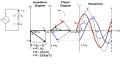
Notice how the voltage across the resistor has the exact same phase angle as the current through it, telling us that E and I are in phase (for the resistor only). The voltage across the capacitor has a phase angle of -10.675o, exactly 90oless than the phase angle of the circuit current. This tells us that the capacitor’s voltage and current are still 90o out of phase with each other.
...
Once again, SPICE confusingly prints the current phase angle at a value equal to the real phase angle plus 180o (or minus 180o). However, its a simple matter to correct this figure and check to see if our work is correct. In this case, the -100.7o output by SPICE for current phase angle equates to a positive 79.3o, which does correspond to our previously calculated figure of 79.325o.
http://digital.ni.com/public.nsf/allkb/388BA7CB2175BA0B8625764100598849
Problem:
I created an RLC circuit in Multisim, and my AC analysis shows a 180-degree phase shift, when my source is 2Vpp, 0 degrees phase shift. I expect to see 0 degree phase shift. Why am I receiving an incorrect phase shift reading?

Solution:
The SPICE model of an inductor consists of a resistor and a current source in parallel. This is not very obvious to the regular eye, as this is coded in the SPICE model and engine. If this internal current source is in the opposite direction, then a 180 phase shift will occur.

To solve this issue, reverse the connections of the inductor.
Phase shift diagrams:
http://macao.communications.museum/eng/exhibition/secondfloor/MoreInfo/2_4_4_PhaseShift.html

2_4_4_6_eng.png
 
Last edited:

DGElder

Joined Apr 3, 2016
351
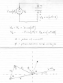
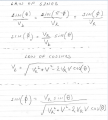
Assuming I didn't goof this up, here is an expression for (phi) the phase difference between the voltages on the plates of a capacitor in this series RC circuit. Setting Va as the reference for 0 degree phase, Vb phase will be equal to phi.

phi = pi - ArcSin(sin(phi))


\\ phase1.png phase2.PNG
 
Last edited:

DGElder

Joined Apr 3, 2016
351
Capture.1PNG.PNG Capture2.PNG


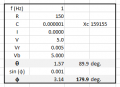
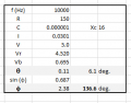
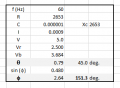
As a check I put the above formula in Excel - solving first for Vr and theta - and plugging in the numbers used in the simulation I mentioned above in post #89. The results match the simulation. And then calculating the Vba phase again with a higher source frequency, the phase changes from about 180 to 137 degrees. 180 deg is the max and 135 deg is the minimum phase difference you can get with differing values of f, C and R. So the math supports my previous qualitative arguments.

Someone might like to run the simulation again at both frequencies to see if my numbers match, just in case you don't trust my calculation 100% - I know I don't .
 
Last edited:
Top