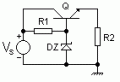
In a shunt regulator the current through the resistor to the zener always carries the same current since the voltage across that resistor is constant, being equal to the source voltage minus the zener voltage.
The current is just divided between the zener and the load.
Thus the more load current, the less zener current, and the better the efficiency.
At low load currents, the zener is carrying most of the current and the efficiency is low, since the supply current hasn't changed.
In a shunt regulator the current through the resistor to the zener always carries the same current since the voltage across that resistor is constant, being equal to the source voltage minus the zener voltage.
The current is just divided between the zener and the load.
Thus the more load current, the less zener current, and the better the efficiency.
At low load currents, the zener is carrying most of the current and the efficiency is low, since the supply current hasn't changed.
when i change the resistor of the load to 20 ohm IL=0.3A that more than the input current
why the current of the load is more than the input ? can you explain to me please
With a 200 Ω series resistor and 20 Ω load resistor, the voltage across the load is (12 V)(20 Ω / 220 Ω) = 1.09 V. Since this is less than the Vz of 6 V, the circuit is NOT in regulation and the zener diode might as well not be there. So the current through the load is 12 V / 220 Ω = 54.5 mA.
What is the largest value that the series pass resistor can be and have the circuit in regulation? Hint: This means no load (zero load current) and just the 100 mA minimum zener current I stipulated in the problem?

 Facebook
 Google
 GitHub
 Linkedin