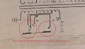
What does this mean of the amplifier?

Status
Not open for further replies.

Thread Starter

Skylar Coy

Joined Apr 29, 2017
133
Insert the speaker jacks.......and observe the switching action.
Any way I can test to see what it currently is doing ?

I think the jacks are drawn a bit weird. I think when you insert the 4 ohm output, it disconnects the 8. It would make sense to do that.

there's a whole bunch of different mono jacks: http://www.switchcraft.com/Category_Multi.aspx?Parent=952 You can see some of the contact arrangements and schematic symbols by looking at the pdf of the mono jacks.
So looking at the schematic how would I wire this. The symbols are just kinda odd. Words help :) haha. Sorry. Just learning.
 
Last edited by a moderator:

BR-549

Joined Sep 22, 2013
4,928
Sure.....turn everything off. Expose the internals of the jack receptacle. Slowly insert jack. Visually watch the switch contacts move as you insert jack.
 

Thread Starter

Skylar Coy

Joined Apr 29, 2017
133
Sure.....turn everything off. Expose the internals of the jack receptacle. Slowly insert jack. Visually watch the switch contacts move as you insert jack.
When nothing is plugged into the left jack, it is using the wire running the fb11 thing the 16 ohm wire is connected to and the wire bridging the jacks, when something is plugged into it it uses com and the wire bridging the two jacks. The other jack has 4 ohm and the wire bridging the two connected. The 8 ohm wire isnt used at all. that concerning to me.
 

BR-549

Joined Sep 22, 2013
4,928
My only comment is on the audio jack. I wouldn't want to comment on this thread topic.......because I can't follow what the TS is talking about.

He uses the original print to describe the problem........but then says the the output transformer has been moded and replaced. He never says what it was replaced with.

Now he says he wants to put it back to original. Can he get the original? And then he says that such a color has such an ohms.

Where did he get that? Is those numbers from a print? or did he isolate transformer and measure?

So...no comment on the topic........but you can check the operation of an audio jack........to understand the switching.
 

Thread Starter

Skylar Coy

Joined Apr 29, 2017
133
My only comment is on the audio jack. I wouldn't want to comment on this thread topic.......because I can't follow what the TS is talking about.

He uses the original print to describe the problem........but then says the the output transformer has been moded and replaced. He never says what it was replaced with.

Now he says he wants to put it back to original. Can he get the original? And then he says that such a color has such an ohms.

Where did he get that? Is those numbers from a print? or did he isolate transformer and measure?

So...no comment on the topic........but you can check the operation of an audio jack........to understand the switching.
I have the schematics for the amp and output transformer. I know which colors are which ohms. The transformer is blown because someone wired it improperly and has been using it wrong. I want to wire it back to the original with the replacement transformer I have. Sorry for the confusion, I'm new.
 

Thread Starter

Skylar Coy

Joined Apr 29, 2017
133
Hello,

@Skylar Coy , Why do you take over the thread of @Pochie45566 ?
You are not the thread starter.

Bertus
Same person. this thread will not appear on the other account so I just signed in through google. I hope my post above made it clear finally what I am trying to accomplish. I am sorry for all the confusion I am just starting to learn about this stuff and this is my second project. Thank you bertus!
 

BR-549

Joined Sep 22, 2013
4,928
I don't mind helping a unfamiliar person with low voltage circuits. But I will not participate in a long distance lesson with high voltage. Your knowledge and vocabulary(understanding terms) is not sufficient. I couldn't trust that our meanings are the same.

For your voltage......I suggest on site and personal consultation. You're gonna get bit....or burn up something.
High voltage across the ears doesn't feel good. Find someone that knows what they are doing. An OLD ham operator or an OLD tv repairman. Tube experience.

Or use a low voltage amp. Not trying to dis-respect you......it's for your safety.

Do you have a brother? Twins perhaps........that's confusing too. See what I mean?

Have you ever heard of the soup nazi? I am the high voltage nazi. No high voltage for you.
 

Thread Starter

Skylar Coy

Joined Apr 29, 2017
133
I don't mind helping a unfamiliar person with low voltage circuits. But I will not participate in a long distance lesson with high voltage. Your knowledge and vocabulary(understanding terms) is not sufficient. I couldn't trust that our meanings are the same.

For your voltage......I suggest on site and personal consultation. You're gonna get bit....or burn up something.
High voltage across the ears doesn't feel good. Find someone that knows what they are doing. An OLD ham operator or an OLD tv repairman. Tube experience.

Or use a low voltage amp. Not trying to dis-respect you......it's for your safety.

Do you have a brother? Twins perhaps........that's confusing too. See what I mean?

Have you ever heard of the soup nazi? I am the high voltage nazi. No high voltage for you.
Would the high voltage not be in the primary of the OT? I guess its more that I do not understand how to wire the secondary of the OT according to the schematic. I drained all the caps and have taken out power and rectifier tubes and all as safety precautions. My confusion came from the outside of the chassis being labeled 8Ω and 16Ω, the schematic indicating 4Ω and 8Ω, the whole 8Ω wire (grey) not being connected to anything which lead me to think it was modified, and the wire running from FB2 to the right output jack which is no where in the schematic. Thank you to everyone helping! If I end up figuring it out ill post my results along with a clip of the amp :)
 

ScottWang

Joined Aug 23, 2012
7,503
Same person. this thread will not appear on the other account so I just signed in through google. I hope my post above made it clear finally what I am trying to accomplish. I am sorry for all the confusion I am just starting to learn about this stuff and this is my second project. Thank you bertus!
Our forum only allowed one person own one ID, please choose which ID that you like to keep and the other one will be deleted.
 
Since everything is messed up, just disconnect the jack and connect the 0 and 8 ohm terminals to a speaker and just see if it works. A tube amp gets very unhappy if the speakers are not connected.

The transformer will look shorted unless your capable of measuring very low resistances.

The symbol does not make a lot of sense and someone could have replaced the jack with the wrong one, There are lots of wiring options and these are mono jacks and not stereo. People might assume that the standard method of internal/external speaker type of contact arrangement is used and it may work.

The 4 ohm output has more current available, thus I would think a 4 ohm out to an 8 ohm speaker is more damaging than a 8 ohm output to a 4 ohm speaker. I hope I got it right.

Independent contacts and ground make the most sense. I didn't re-read everything and double check my answer/
 
Status
Not open for further replies.
Top