Facebook
 Google
 GitHub
 Linkedin
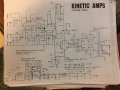
That means it just connects elsewhere i guess. So I can just swap the 4 ohm and 18 ohm leads and Ill be fine. I will have 16 and 8 ohm jacks correct? even with the 8 ohm being by itselfIn the circuit the 16Ω was labeled as F.B.II, so it should be connecting to somewhere, if you can draw the wiring of 16Ω then it will be more clear.
What does this mean of the amplifier?
- Thread starter Skylar Coy
- Start date


 then you just click the big 'S' on the right top of the message box, it is a toggle function.
")