lower and noisier output is ok as long as there is any output at all, so how to create the field with capacitive coupling to the body at audio frequency?
Flasz, you are talking about the body used as an antenna to pickup audio frequencies and many amplitude noises like all the pops, clicks and buzzes heard on AM radios. Of course you need to amplify then demodulate the AM pickup and remove the low frequency 50Hz or 60Hz and its harmonics to make tinny music sounds.
You can hear all the audio AM interference when you connect a single input wire to an audio amplifier. Connect that wire to your body. Turn down the bass control to hear the higher frequency pops, clicks and buzzes.
No. It's not demodulating the AM signal in the body. But only the capacitive coupling. BobTPH described it exactly:
"The AC line frequency is coupled to the body because the body is surrounded by wiring carrying high currents at that frequency.
Sure, could do the same with audio frequencies by surrounding the body with wiring carrying large currents at audio frequencies.
You could also pick this signal up by attaching an electrode to the skin. You would need a ground reference as well to get a good signal.".
BobTPH also said low current is possible but lower and noisier output. Note the distinction this is not the AM radio thing using the body conductive channel but capacitive coupling only.
It may be hard to build the audio frequency capacitive coupling source. So I'll just stick to one or two frequencies. How do you create 600 Hz and 800 Hz of capacitive coupling source so my ECG modified to higher frequency can pick that up from the body using electrode?
Flasz, you did not hear me.
An ECG circuit cancels 60Hz and any other interference frequencies (like your transmitted 600Hz and 800Hz when modified).
The signal that is capacitively-coupled to the body will be extremely small and will need a high gain amplifier.
Then earphones can play the sounds and interference.
For years, some churches and conference rooms have used wireless communication by transmitting a magnetic signal in a loop of wire around the room making magnetic signals. It is picked up by hearing aids made for it or a magnetic sensor, amplifier and earphones.
I have already made a modified ECG circuit that doesn't cancel 60 Hz. That is. It doesn't have any right leg drive. The frequency is also increased from 40 Hz cutoff to 30 kHz cutoff.
Btw.. in normal ECG which has already good CMRR, why can't it already remove the common mode 60 Hz and still need a right leg drive to further decrease it?
So you mean the transmitted 600 Hz/800 Hz would be much smaller than the 60 Hz AC capacitive coupling?
An ECG circuit cancels common-mode signal (usually equal strength on both signal wires) with good common-mode rejection of its instrumentation amplifier and more rejection by inverting the common-mode signal and feeding it to the patient's right leg. The in-phase and out-of-phase signals cancel.
Your transmitted capacitor-coupled signal will be common mode. If you use an ECG circuit then your transmitted capacitor-coupled signal will be cancelled.
Is there no way to disable the CMRR of an op-amp or instrumentation amp? If no way. Then what amplifier just I use that won't reject the common mode signal but yet can amplify the differential mode signal?
The differential inputs inputs on an opamp or instrumentation amplifier produce pretty good common mode rejection. That is why they are used for an ECG or brainwave circuit, the heart and brain signals are differential.
Your body used as an capacitor-coupled antenna will not use an amplifier with differential inputs.
Any amplifier with a single input (plus ground as reference) has no common mode rejection. It will pickup a lot of interference.
So how do I produce 800 Hz capacitive coupling in the body? What source transmitter/circut can you suggest? It must be so low current that it won't hurt you even if you accidentally touch the wire. It won't be worth for me to try 800 Hz AC and risk it.
I think capacitance-coupling to your body needs to use your distance from one wire plus the high voltage in the wires to do it since it still works with no current in the wires.
High voltage? Ok I won't do the capacitive coupling transmitter anymore.
How come ordinary Instrumentation Amp can't remove the 60 Hz common signal and you still need the right leg drive? What INA chip where the common 60 Hz can be removed without any right leg drive? If none, why can't they make it?
Suppose your idea works (unlikely). How is it better than what is used today? You can come up with innovations all day long, but if you can’t show they are better, they are worthless.
An ECG can cancel out the 60Hz because it is at the same same level at each electrode. But your audio is also at the same level everywhere.
Also, it is out of the frequency range that the ECG is looking for. It is within the range that your audio device requires.
The signal that the ECG wants is the difference between two electrodes. That is not the case with your audio. That is why the techniques used for ECG do not apply. Stop thinking that they do, it will get you nowhere.
The human heart beat is usually 60Hz so they want to remove as much of the interference on an ECG circuit as they can.
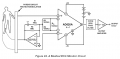
An old AD620A was and is used as an ECG amplifier. Its common-mode rejection is a minimum of -80dB which is 1/10000 in this ECG circuit:
I'm making an EMG and want to remove all contribution of heart, that is why if there is an INA that can totally eliminate the 60 Hz, the better. Is there? What is it?
Also I need to make the EMG at least 10 kHz cutoff. In needle EMG, they use 10 kHz. So I want my EMG to have 10 kHz cutoff not for use in needle EMG but I just want the cutoff to be high.
An EMG is a display of a nerve signal driving a contracting muscle. The heart is a muscle contracting at around 60Hz but its nerve electrical activity is probably not being observed then might not show in the EMG of a different muscle.
Wikipedia shows an oscilloscope with bursts of EMG signals and a rectified signal of the bursts. The frequencies in each burst are from 7Hz to 20Hz. It says the burst voltages are from 50uV to 30mV depending on the muscle observed. Wikipedia does not say whiich frequencies are in the bursts but the display shows sharp peaks that probably have fairly high audio frequency harmonics and they say the bursts can be heard on an audio amplifier.
An IMA will not cancel signals from the heart because the heart signals are differential which is what an IMA amplifies. The EMG signals are also differential. It is the 60Hz interference from electricity that is common-mode that an IMA cancels.
I guess you can use an analog filter to remove any 60Hz interference from the heart or from electricity.
Do you know what Instrumentation Amplifier they used? Or did they fabricate their own INA?
The popular AD8232 is one chip but only for ECG. I need the most sophisticated integrated chip for EMG. Is there one?
Btw. Did you live in the year 1970. At that time, what was the noise of their amplifier used in EMG? What was the baseline noise compared to current 1microVolt? Could the noise be in milliVolt? I need to know. Thanks.
In 1970, the 741 opamp was one of the first opamps. It was introduced in 1968 and produced plenty of noise and had a poor audio high frequency slew rate. An INA has 3 or 4 opamps inside it. In 1970, recorded music was played on a record player. Its preamp and power amp used transistors, not integrated circuits.
I doubt that an INA or EMG device was available in 1970.
"It all started in 1950 with the introduction of the first commercially available electromyography (EMG) system. From 1950 to 1973 was the era of the analog EMG systems: EMG signals were recorded, and subsequent analyses were carried out manually on film or paper. From 1973 to 1982, the first modular digital EMG systems were introduced. Dedicated analysis modules were introduced, but detailed analysis was still done on paper. In 1982, the first system controlled by a microprocessor was introduced. From 1982 to 1993, many new ways of analyzing EMG signals and basic reporting features were implemented in the EMG systems. Since 1993, personal computer technology has been used in EMG systems. Standard software and hardware components are used to record, analyze, and document EMG examinations. Since 1950, many people have influenced the development of new features in commercial EMG systems. However, within the last 3 decades, Erik Stålberg has always been in the forefront and has shown ways of implementing new methods for analyzing EMG activity or nerve signals. The development of new commercial EMG systems has been dependent on the technology introduced to the market at that particular period of time. This article only refers to systems that have been sold or are now being sold worldwide."
So the EMG before 1970 was made of transistors?
What was the noise levels of transistors if used in EMG? I wonder where to find this info. I want to build an antique EMG just out of curiosity and interests.
 Facebook
 Google
 GitHub
 Linkedin