Facebook
 Google
 GitHub
 Linkedin
Hi guys,
I opened this thread with the intention of posting progress as well as posing questions related to this project to minimize congestion on the main board.
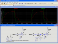
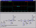
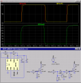
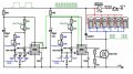
I'm building the Dave Lawton D14 dual 555 timer circuit in the pic. This is my fourth PWM design constructed. I had originally avoided this one because it was popular but apparently had only worked for one guy. Did anyone else do a correct replication? If a few did, would they come forth?
My current problem is this -- I have 4 variable resisters in this circuit. Mine are 5mOhm linear taper pots, 3 contacts. I crossed the middle and an outside contact, then ran wire from the two outside contacts to the board. I realized I was only getting at max 1.6 mOhms. However, in this method, the adjustable frequency range of the circuit is drastically increased.
When I broke the contact between pins 1 and 2 on the pot, and ran wires from 1 and 2 right to the board, the resistance range increased to 5mOhms again, but output frequency range decreased.
What am I missing here? Shouldn't higher range of resistance equate to higher frequency range? How do the pot contacts work?
Thanks for all help and feedback on this project. I was just fired, and could really use a revolutionary technology.
Regards
Farlander
I opened this thread with the intention of posting progress as well as posing questions related to this project to minimize congestion on the main board.
I'm building the Dave Lawton D14 dual 555 timer circuit in the pic. This is my fourth PWM design constructed. I had originally avoided this one because it was popular but apparently had only worked for one guy. Did anyone else do a correct replication? If a few did, would they come forth?
My current problem is this -- I have 4 variable resisters in this circuit. Mine are 5mOhm linear taper pots, 3 contacts. I crossed the middle and an outside contact, then ran wire from the two outside contacts to the board. I realized I was only getting at max 1.6 mOhms. However, in this method, the adjustable frequency range of the circuit is drastically increased.
When I broke the contact between pins 1 and 2 on the pot, and ran wires from 1 and 2 right to the board, the resistance range increased to 5mOhms again, but output frequency range decreased.
What am I missing here? Shouldn't higher range of resistance equate to higher frequency range? How do the pot contacts work?
Thanks for all help and feedback on this project. I was just fired, and could really use a revolutionary technology.
Regards
Farlander
Attachments
-
 65.3 KB Views: 530

 You should have them stored in either static-safe bags, conductive foam, or the good old hobbyists' standby, aluminum foil.