Well pump electircal circuit with 3 switches

Thread Starter

yousefomar

Joined Nov 14, 2018
2
Hello all.

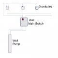
I'm trying to figure out an electrical circuit, how to connect a Well Pump to be switched on/off from 3 switches. each one of the switches can turn on/off the pump.

The use case for this is 3 houses sharing one water well. each house should be able to turn on the pump to fill-in their tank. so it's not "toggle", where one switch will turn the pump on, and the other off.

these will not be manual switches, each tank will have an automatic floating switch which will turn-on when the water hits a low level in the tank, and off when it reaches a high level.

I came up with a diagram (attached), and I would like to know if this is the right way to do this? and if there will be an issue/shortage if 2 or more switches turned on in the same time ?

appreciate your feedback.

Youssef
 

Attachments

MaxHeadRoom

Joined Jul 18, 2013
30,589
So you mean 1 pump for 3 house tanks. and each house can switch on/off?
Seems like a conflict there.
What if one tank is full, and switch the single pump off, so the others won't get serviced?
Max.
 

drc_567

Joined Dec 29, 2008
1,156
Suggestion ... centralize the storage reservoir somehow, so that only one switch and level sensor is used to fill and pressurize the unit. Connect piping from that central location to the individual houses.
 

LesJones

Joined Jan 8, 2017
4,511
When the pump is running is the flow divided equaly between the three tank or is there also solenoid/motorised valve allowing the water to enter each individual tank ? So for example if two tanks required filling would the logic be running the pump and opening two valves ?

Les.
 

Thread Starter

yousefomar

Joined Nov 14, 2018
2
thanks for the input guys. we are planning to use mechanical valve on each tank, to stop the water from flowing into a full tank. so the water will only flow to the tanks which not full.
 

Tonyr1084

Joined Sep 24, 2015
9,744
It appears as your switch configuration is correct. For those wondering what happens if two homes are at full capacity and one home demands more water - the tank with the lowest pressure will take up the incoming water. Once all three tanks are equalized the pump will shut off. I don't see any conflict - BUT I don't have any practical experience with this arrangement. I'm basing my answer off of what seems logical.

Each tank has a single pole single throw switch (pressure switch). When water pressure is low the switch applies power (CRITICAL: FROM THE SAME ELECTRICAL SOURCE) to the pump. All three tanks will be topped off but the pressure in all three tanks should reach equilibrium.

I'm ASSUMING there is back flow preventers to prevent my tank from draining because you want to water the garden excessively and shower 10 times a day (exaggerated purposefully). Without back flow valves all three tanks can be emptied by a single user, and that would be a huge problem.

So if there are back flow valves on each water line circuit then if one tank is at 60 PSI (again, assumed), one tank is at 50 PSI and the third is at 35 PSI - the pump should come on. The tank with the lowest pressure should run the pump until it reaches 60 PSI.

OR IF YOU WANT TO GO EVEN MORE CONTROLLED: Each tank is not only connected to the pump but each tank also has an electric inlet valve that only opens when THAT SPECIFIC TANK demands water. Which would mean that every time you deplete your water supply mine remains constantly at whatever pressure it was at when the pump came on. Thus water is directed only to the tank demanding a refill. But in that instance you'd need a double pole single throw pressure switch. I'd imagine they make them. When your tank needs water the pump is turned on at the same time the valve is opened. Your neighbors are unaffected by your usage and needs.
 

Tonyr1084

Joined Sep 24, 2015
9,744
AGAIN, LET ME BE CLEAR BY WHAT I MEAN WHEN I SAY "FROM THE SAME ELECTRICAL SOURCE". In the US, we typically have 240 service coming into the house and it is split into two services, each of 120 VAC, commonly identified as LEG A and LEG B. If you inadvertently connect one pump switch to leg A and another pump switch to leg B, if they both come on at the same time you'll have a 240 volt dead short. And something is going to go poof in a big way.
 

MisterBill2

Joined Jan 23, 2018
27,269
If the switches are actually connected as shown, it will work well, since each tank has a float valve to prevent an overflow. The flow will probably be able to fill all three tanks at once, but not all at the same rate, but the rate should not matter. You could use three float switches and make the whole system automatic. And all of Tony's precaution suggestions are valid.
I suggest that each house have some indicator to show when the pump is running, so that you may recognize a situation when something is not right.
 

MrSoftware

Joined Oct 29, 2013
2,273
Your circuit looks good. Maybe it would be clearer if you reword your question to yourself. Instead of "how to connect a Well Pump to be switched on/off from 3 switches" word it like "how to turn on the well pump when any one of 3 tanks gets low".
 

MisterBill2

Joined Jan 23, 2018
27,269
Your circuit looks good. Maybe it would be clearer if you reword your question to yourself. Instead of "how to connect a Well Pump to be switched on/off from 3 switches" word it like "how to turn on the well pump when any one of 3 tanks gets low".
The system is evidently not automatic, and so it is a user decision to run the pump or not. The title was adequate, better than a lot of titles, in that it did convey correct information. Even better, the explanation was totally adequate for us to evaluate and answer the question. I am guessing that this is a project replacing a situation where each house had a well that became unusable, and that the expense of three new wells to a much greater depth was a much larger expense. So sharing one well makes a great deal of sense, while going to one single central tank would be a much more expensive project requiring a whole lot more cost and effort. Been there so I am aware. The new deeper pumps cost a lot more than a few hundred feet of 1/2 inch poly water line.
 

MrSoftware

Joined Oct 29, 2013
2,273
I wasn't taking a dig at his title, I was just trying to help him simplify his question which would make the correctness of his own answer more obvious. The "off" part of his question is not necessary as off is the default state of the system. He only needs to worry about forcing the "on" state. When you think about it this way, the 3 switches in parallel is clearly OK. :)

Having grown up on well water (and the pump always seems to break down when someone is in the shower or there's a line for the bathroom); typically there is a pressure switch on the high pressure side of the check valve. The switch toggles the pump on and off as required by the pressure changes. It would be logical in his case to have 3 pressure switches and 3 check valves, otherwise he wouldn't need 3 switches. It would make more sense for a new install to use a single larger tank, but perhaps all the other equipment is already in place?
 

Tonyr1084

Joined Sep 24, 2015
9,744
@Dodgydave I think I have to disagree with your solution. My thinking is that if my tank needs water and yours doesn't it negates the running of the pump. I'm not quite following your diagram but if one switch can turn the pump on and the other turns it off - unless both switches are in the proper orientation they shut the pump off.

Perhaps you can explain it and maybe clear up any confusion on my part. For my money, three SPST switches in parallel acting like an OR gate should be able to control the pump perfectly. If one tank needs water the pump runs. If the second tank requires water while the pump is running there is no electrical change in potential at the pump and the pump continues to run. If, for some reason, the third tank needs water, again, I think your solution changes the potential at the pump. That looks like a 4 way switch in the middle. Correct me if I'm wrong but if my tank needs water and then yours does too, doesn't that shut the system down?
 

MisterBill2

Joined Jan 23, 2018
27,269
Tony is certainly right!! 3-way switches are about turning the light off, not about turning it on. AND it is not about only one needing to use the pump, it is about any of the three needing to start it, and it gets switched off when none of the three need it. When designing a control system, even a very simple one, it is vital to understand the requirements. The second thing to note, which has been ignored by some, is that each user already has a tank to be filled, so that gravity delivers the water. That is important because in some parts of the world power is not available 24 hours a day, nor is water. The well solves the availability problem and the individual tanks solve the power availability problem. So while a different arrangement with a common tank would work in a commune being constructed today, existing tanks and plumbing make more sense because they are all ready paid for.
 

Tonyr1084

Joined Sep 24, 2015
9,744
@MisterBill2: Somewhere back in the thread I mentioned check valves - maybe I called them reverse flow valves or something like that. The purpose of check valves (in this case) would be to prevent one user from draining all three tanks. I went on to suggest the use of an electric valve that would only open when that specific tank required water. In such an arrangement, tank A (assume 60 PSI) is full and not demanding any water. Tank B is at 50 PSI. It's not full but not demanding any water. Tank C is below 40 PSI and needs water. Tank C turns the pump on and opens the valve for tank C. It fills to 60 PSI and shuts the system off. Tank B is still at 50 PSI because it did not demand any water. As a result, tank C filled quickly. If we were to use check valves all three tanks would be topped off anytime any of the tanks dropped below 40 PSI. That means the pump is now sending water to all three tanks at once, and the tank most in need has to wait longer till full. Naturally, the tank with the lowest pressure will take the lion's share of the water, but it still takes longer because tank B (in my example) was at 50 PSI. Using check valves eliminates one potential point of failure but it also sacrifices fill times; whereas tanks with electric valves would allow the tank demanding water to fill as quickly as possible, depending on the flow rate of the pump.

Electric valves may also be more advantageous in that if the well is running low on water, filling everyones tank at the same time may become problematic. Whereas, if tanks A & B use much less water than C then the well only has to supply water where needed the most. So what if tanks A & B are sitting somewhere close to but above the switching point. If the users are not demanding water then why ask the pump to fill all three tanks at once. Still, electric valves further complicates the setup. My personal opinion is that electric valves is the way to go.
 

MisterBill2

Joined Jan 23, 2018
27,269
@MisterBill2: Somewhere back in the thread I mentioned check valves - maybe I called them reverse flow valves or something like that. The purpose of check valves (in this case) would be to prevent one user from draining all three tanks. I went on to suggest the use of an electric valve that would only open when that specific tank required water. In such an arrangement, tank A (assume 60 PSI) is full and not demanding any water. Tank B is at 50 PSI. It's not full but not demanding any water. Tank C is below 40 PSI and needs water. Tank C turns the pump on and opens the valve for tank C. It fills to 60 PSI and shuts the system off. Tank B is still at 50 PSI because it did not demand any water. As a result, tank C filled quickly. If we were to use check valves all three tanks would be topped off anytime any of the tanks dropped below 40 PSI. That means the pump is now sending water to all three tanks at once, and the tank most in need has to wait longer till full. Naturally, the tank with the lowest pressure will take the lion's share of the water, but it still takes longer because tank B (in my example) was at 50 PSI. Using check valves eliminates one potential point of failure but it also sacrifices fill times; whereas tanks with electric valves would allow the tank demanding water to fill as quickly as possible, depending on the flow rate of the pump.

Electric valves may also be more advantageous in that if the well is running low on water, filling everyones tank at the same time may become problematic. Whereas, if tanks A & B use much less water than C then the well only has to supply water where needed the most. So what if tanks A & B are sitting somewhere close to but above the switching point. If the users are not demanding water then why ask the pump to fill all three tanks at once. Still, electric valves further complicates the setup. My personal opinion is that electric valves is the way to go.
Yes, a fully automatic system with level sensors and solenoid valves would be great, and cost quite a bit. The thread starter already mentioned that each tank had a float valve to avoid over flowing the tank. So it is not likely that pressure switches are an option, since the tanks are located above the house to allow for gravity flow. And at the present price of solenoid valves suitable for residential water service that would add a big chunk of cost to the project.
The whole goal of the project was to allow one pump to serve three households, the unstated but obvious to me, it seems, goal was minimum cost, since deeper wells and deep well pumps cost quite a bit. And the proposed system in the drawing does fill all of those requirements. My only suggestion still holds, which is to add an indicator for when the pump is running.
 

Tonyr1084

Joined Sep 24, 2015
9,744
@MisterBill2: Apparently I was under the impression we were talking about a conventional modern well water system where the tank was one with a diaphragm and a pressure switch. I must have missed the part about the tank being elevated and gravity fed. In that case, yes, electric valves would be a wasted expense. I will re-read the threads.

[edit] Yup! Right there in the first thread. I guess I read too fast or got fixated on the notion we were discussing modern well water systems. Sorry. Can I get another Darwin Award now?
 

MisterBill2

Joined Jan 23, 2018
27,269
@MisterBill2: Apparently I was under the impression we were talking about a conventional modern well water system where the tank was one with a diaphragm and a pressure switch. I must have missed the part about the tank being elevated and gravity fed. In that case, yes, electric valves would be a wasted expense. I will re-read the threads.

[edit] Yup! Right there in the first thread. I guess I read too fast or got fixated on the notion we were discussing modern well water systems. Sorry. Can I get another Darwin Award now?
It is not a big deal and if you were not aware of how things get done in other parts of the world it would not be obvious at all. The modern city like that is in Israel, where the modern water tanks all sit high above the houses. AND, also in Mexico, including the modern hotels in Mexico City.
 

Dodgydave

Joined Jun 22, 2012
11,395
@Dodgydave I think I have to disagree with your solution. My thinking is that if my tank needs water and yours doesn't it negates the running of the pump. I'm not quite following your diagram but if one switch can turn the pump on and the other turns it off - unless both switches are in the proper orientation they shut the pump off.

Perhaps you can explain it and maybe clear up any confusion on my part. For my money, three SPST switches in parallel acting like an OR gate should be able to control the pump perfectly. If one tank needs water the pump runs. If the second tank requires water while the pump is running there is no electrical change in potential at the pump and the pump continues to run. If, for some reason, the third tank needs water, again, I think your solution changes the potential at the pump. That looks like a 4 way switch in the middle. Correct me if I'm wrong but if my tank needs water and then yours does too, doesn't that shut the system down?
It's a Three Way Circuit. each switch can turn the pump on or off , the other option is three parallel switches at each house then you can't turn off the pump unless all switches are open...
 
Top