hi T,
Do NOT connect pin #15 directly to +5V.!
I have just added a 2K pull up to pin #15 and it is still showing 0V, which most likely means that pin #15 is connected to the PCB's copper 0V rail.
E
hi T,
Do NOT connect pin #15 directly to +5V.!
I have just added a 2K pull up to pin #15 and it is still showing 0V, which most likely means that pin #15 is connected to the PCB's copper 0V rail.
E
This is one method, I will try it.
Clip from link: I manage to get 80hz output from hx711 . I lifted pin 15(RATE) and soldered with 10k resistor to 5V.you get 80 hz output.
E
hi T,
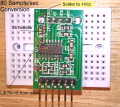
Conversion from 10Samp/s to 80Samp/sec done, works OK,.!
Using a small safety pin, form a very small hook on the sharp end of the pin.
Place hook under pin #15 , apply your solder iron to pin 15, , gently prise the HX711 leg, upward off the PCB pad, leave a gap of approx 1mm between the leg and the PCB.
Cut a 0.125W 1k thru 10k resistor to length [ the 0.125Watt resistor have thinner connecting wires]
Carefully scrape the copper track clean, removing the green lacquer, tin the track.
Solder in the resistor.
Refer to attached image for directions.
It is important that you ensure that you do not cause damage to the HX711 IC, so observe electrostatic procedures.
sorry dont undetstand. i try to put it in other words.
i solder a 1k and a 10k resistor in series (to have total 11k)and solder it to pin15 and connenct the other side to 5v. why shall i work on the copper tracks?
hi,
When I say 1K thru 10K, it means any resistor value between 1K and 10k that you have available.
The 2K value is a 0.125Watt rated resistor, note its small physical size.
A higher wattage resistor [bigger] will be OK, but it will be difficult to get an easy fit.
You cut the wires of the resistor to a length that will make it easy to fit.
The reason for connecting to the Vdd +5v track is so that you can use the onboard 5v
The image I posted should make it easy to follow.
E
it works well! I´m currently soldering the matrixes. I wonder what difference it makes if I have two LCs going to A- and the other to A+ or just one to A- and the other three to A+.
It changes kind of the voltage offset right?
hi T,
You can connect two L/C's in parallel, ensure that signals are in phase, ie: when applying a weight, the positive going signals are additive, likewise for the negative going signal wires.
I am assuming that the two L/C's are physically mounted on the same segment of the pie cut Base plate.
You cannot connect one A- and three A+ together, as you have stated, the added signals would not give a correct weight.
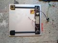
one loadscale with four sensors is for each segment, as you can see on the picture in the recent post.
I have now identical circuits for each segment but some sending a negativ voltage without any pressure and some a positiv? is that ok? I still can read them out correctly later, because they are all additive.
Lets refer to the new ones:
The serial monitor shows the value I´m receiving with no load.
The circuits are identical. but some send positiv some negativ values.
hi T,
Are the 4, half bridge load cells mounted on the same base plate section.??
Also are they wired as per the attached diagram.? if so, check the sense of the signals from each L/C compared to the other cells, when in compression..???
E
If I wire like in the attached diagram, the L/C values which go to A- are increasing when compressed and the L/C values which go to A+ are decreasing when compressed. Thats why I inversed polarity on those which go to A+. In 3 of 5 cases I´m having a positiv offset, but I dont understand why...
You could do a little post processing in the Arduino, converting the bit streams into say a ASCII value, which could be moved out as a serial TTL/RS232 string to the max msp.
E
when i´m recieving six L/Cs at the same time, always one of the six values is very jittery and its not representing any value to a weight.
Would it be a solution to do this conversion to a string you mentioned above to have more stable values?
What type of value am I receiving now? Its not a bit stream.. someting like a standard long? its more or less +-1000000...
yes it swaps, the *error* is independent of the LCs. it has to do with the amount of L/Cs.
Another question would be how i can set index and order of the L/Cs. index changes with every start of the serial connection.
 Facebook
 Google
 GitHub
 Linkedin