weighing scale circuit

Thread Starter

TillFly

Joined Oct 26, 2016
69
Hi E!

I am assuming that your Arduino is being powered by either a 5v from a USB or the onboard 5V reg with say a 9V DC source.?? [battery?]
E
yes, 5v from a USB

The L/C is a nominal 1K load resistance, so 5 in parallel would be a 200R load, at say 5V, that is 25mA

I cant follow your calculation:
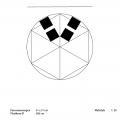
I I use 6 load scales. (Its easier then to calculate the xy postition)
So its 1 K for each L/C?
1K * 4 * 6 = 24 K
u/r=i;
5V/24K= 208,33 mA ?

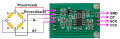
The HX bypass transistor will be OK for this current level.
Is this transistor in the hx711 module? what does it?

The HX711 will also accept a 5V power source, taking approx 1.5mA for its internal circuitry.

Are there any other modules in the project.??
No other modules in the project
 

ericgibbs

Joined Jan 29, 2010
21,448
hi T,
Your L/C's are connected in parallel, as each L/C is equivalent to a 1K resistance, when you connect two in parallel the combined resistance will 500R.
Connecting 5, 1k resistors in parallel would be 200R. [ 6 is 166.67'R]

The HX711 bypass transistor should be already mounted on the HX PCB, check the track from the HC711 I/C Pin #2 , labelled Base, it should have a transistor connected.
The transistors purpose is to supply the L/C with the required excitation voltage, which is set by the VFB pin.

Look at these images.

OK.?
E

EDIT:
Added HX711 PCB image, Q2 at the top edge is the bypass transistor
 

Attachments

Last edited:

Thread Starter

TillFly

Joined Oct 26, 2016
69
Thanks a lot E!

The amps a still not there to test :(

My concept for the load scale changed slightly and now I another idea/question arises.

First a short recap of the infos:
My weighing platform is round with a diameter of 2m.
Due to the fact that I want to use it as I kind of interactive floor I want to split the weighing platform in six equal parts to get seperate force effects.
For each slice I´m interested in the excentric position of the force, thus I would like to have 2 L/Cs in a line for each slice.
Depending where the resulting force on the slice is, it should be possible to detect the excentric position with the ratio of the both L/Cs.

Now I´m wondering where I should measure this ratio?
If I would read out the L/C signals first with the arduino, I need 12 analog inputs on the arduino and I dont know whether the serial stream will deliver me fluent data with 12 channels.
Thus my idea is to substract the voltage of one L/C from the other L/C of the same slice and just read out the rationed voltage to stay with 6 analog inputs.

How could I do this?

I hope my idea is comprehesible.
In the pic you can see the two L/Cs for two slices.

Best,
D
 

Attachments

ericgibbs

Joined Jan 29, 2010
21,448
hi D,
I guess you are planning to use one HX711 for each L/C.?
This would mean 12 Digital inputs to the Arduino, as the HX data output is a bit stream.
[ determine the total 5V loading of the Arduino due to 12, HX and L/Cs]

When you are comparing the weight of 'pie/sector ' sections are you measuring for an absolute weight per pie or a relative distribution of the pies in order to determine the imbalance of the applied weight.?

Is this project to determine the eccentric imbalance of a heavy vehicle tyres.?

E
 

Thread Starter

TillFly

Joined Oct 26, 2016
69
Hey E,

I guess you are planning to use one HX711 for each L/C.?

Yes

This would mean 12 Digital inputs to the Arduino, as the HX data output is a bit stream.
[ determine the total 5V loading of the Arduino due to 12, HX and L/Cs]

I used the analogIn for my first L/C test and it worked. How can this happen? analogIns range from 0 - 1023 and digitalIns have a certain threshold and detect 0 and 1?
I have to check if its also working with digitalIns. So far I don’t understand how it´s programmed in the h. and cpp. files of the arduino library.
(HX711_master library for arduino attached.)

When you are comparing the weight of 'pie/sector ' sections are you measuring for an absolute weight per pie or a relative distribution of the pies in order to determine the imbalance of the applied weight.?
I´m measuring not on static object and no heavy vehilce types. People will stand on this load scale. So its possible that only one Person stands on one slice or e.g. many people stand across all slices.
In all cases I would like to have:
- total weight
- weight per slice
- eccentric factor per slice

Does it answer your question?
 

Attachments

ericgibbs

Joined Jan 29, 2010
21,448
hi T,
On a MCU/PIC etc, the Analog input pins can be programmed as Analog or Digital inputs.
So I would expect the HX/Arduino program to have set them to Digital Inputs.

If the program reads all the HX data, from the 12 L/Cs, it should be possible to calculate the 3 parameters you are asking.

Are you writing all the Arduino calc programs.?

E
Out of interest, why would you want to measure these parameters.?:)

EDIT:

This clip from your zip shows the digital pin I/O
void HX711::begin(byte dout, byte pd_sck, byte gain) {
PD_SCK = pd_sck;
DOUT = dout;

pinMode(PD_SCK, OUTPUT);
pinMode(DOUT, INPUT);


set_gain(gain);
}

bool HX711::is_ready() {
return digitalRead(DOUT) == LOW;
}
 

Thread Starter

TillFly

Joined Oct 26, 2016
69
Hey E,

If the program reads all the HX data, from the 12 L/Cs, it should be possible to calculate the 3 parameters you are asking.
Are you writing all the Arduino calc programs.?

I would prefer to route all the 12 signals from arduino to another program called max msp. There I´m more versatile for handling the calculations.
So I need to do the i/o routings in arduino to get all the signals...
concerning the code:
I would send the same PD_SCK clock from the mcu to all the hx711 modules and setup DOUT_1, DOUT_2, .. etc. .
Then passing the signals to max msp via serial communication.

Out of interest, why would you want to measure these parameters?
I´m a sound designer and I want to build an instrument which can be played by several people. My main aim is that people come closer to each other while exploring the sound mechanisms of the instrument. this is my bachelor thesis. Nothing to do with vehicles, I hope you´re still with me :)
 

ericgibbs

Joined Jan 29, 2010
21,448
hi T,
Sounds fascinating, no pun intended.:rolleyes:
The Arduino will have to access each of the 12 HX bit stream messages sequentially, so I guess you will store all 12 samples and then serial output them sequentially to the max msp.
You could do a little post processing in the Arduino, converting the bit streams into say a ASCII value, which could be moved out as a serial TTL/RS232 string to the max msp.

Lets know how it goes.
E
 

Thread Starter

TillFly

Joined Oct 26, 2016
69
Hey E,

where in the code is it declared which analog port is in- or output ( in numbers as A0 and A1..)?
In the arduino sketch there is just the comment:
// HX711.DOUT - pin #A1
// HX711.PD_SCK - pin #A0

and in the .ccp is no number..

void HX711::begin(byte dout, byte pd_sck, byte gain) {
PD_SCK = pd_sck;
DOUT = dout;

pinMode(PD_SCK, OUTPUT);
pinMode(DOUT, INPUT);

set_gain(gain);
}
 
Last edited:

ericgibbs

Joined Jan 29, 2010
21,448
hi T,
I wrote my HX711 programs based on the 18F4520, using Oshonsoft Basic.
I have a some Arduino UNO's on the bench so I will create a Arduino sketch using the HX711.

E

Have you noticed this text from the zip.
# How to use
See the example in examples/HX711SerialBegin.
Please don't use examples/HX711Serial anymore.
It is deprecated because the pin definition within the constructor is not timing safe. (#29)

;clip from serialbegin.ino

Serial.println("Initializing the scale");
// parameter "gain" is ommited; the default value 128 is used by the library
// HX711.DOUT - pin #A1
// HX711.PD_SCK - pin #A0
scale.begin(A1, A0);
 
Last edited:

Thread Starter

TillFly

Joined Oct 26, 2016
69
Hey E,

yes I read the #howtouse part and I just use the HX711SerialBegin.ino.
The Oshonsoft Basic looks pretty advanced to me. I think the arduino enviroment would be better.

So if I want to add inputs to the sketch and I guess I need to start editing the library right?
So as a test with two L/Cs I added a DOUT_2 and renaming the first one DOUT_1.


I started editing the header file:

class HX711
{
private:
byte PD_SCK; // Power Down and Serial Clock Input Pin
byte DOUT_1; // Serial Data Output Pin 1
byte DOUT_2
; // Serial Data Output Pin 2
.....

as well as in the

public:
void begin(byte dout_1, byte dout_2, byte pd_sck, byte gain = 128);


in the source file I edited:


HX711::HX711(byte dout_1, byte dout_2, byte pd_sck, byte gain) {
begin(dout_1, dout_2, pd_sck, gain);
}

HX711::HX711() {
}

HX711::~HX711() {
}

void HX711::begin(byte dout_1, byte dout_2, byte pd_sck, byte gain) {
PD_SCK = pd_sck;
DOUT_1 = dout_1;
DOUT_2 = dout_2;


pinMode(PD_SCK, OUTPUT);
pinMode(DOUT_1, INPUT);
pinMode(DOUT_2, INPUT);
// second input added in variables off function

set_gain(gain);
}


Is this the way to go? So far I got many error messages I have to figure out..

I would like to understand how the pin assignment with the function scale.begin() works.
Would DOUT_2 with
scale.begin(A2, A1, A0) then be A2?
 

ericgibbs

Joined Jan 29, 2010
21,448
hi T,
I would recommend initially using just the scale.begin(A0, A1); with one HX711 module, get that to compile and work.
If it runs OK, then try say just A2,A3 as a further check [ change the A0 and A1 to scale.begin(A2,A3);

This should give confidence in the lib files etc.

E
 

ericgibbs

Joined Jan 29, 2010
21,448
hi T,
I have built a HX711 with a Arduino UNO, but the Sketches within the HX711 zip you posted will not compile, many errors.
Are you able to compile them.??
All my other project Sketches work OK.
E
 

djsfantasi

Joined Apr 11, 2010
9,237
Nevermind...

I had a question? I am not familiar with the HX711. Does it have an analog or digital output? It's not clear to me from the description. And your application will use an analog or digital output? Likely digital, because analog output requires external circuitry and possibly multiple pins.

My concern is that with the Uno alone, you're going to need 24 pins. And the Uno doesn't have that many...

UPDATE: I somehow had the misguided impression that you were using 12 sensors. It still may be a concern because there are only 6 ADC pins. Although there is an unsupported way to get 6 more.
 
Last edited:

ericgibbs

Joined Jan 29, 2010
21,448
hi T,
Tried erasing and re-installing Arduino 1.8.2 for Arduino UNO.
Now I cannot even get my earlier programs to compile.
A bad hair day.!
I will try my other PC tomorrow.
E
 

djsfantasi

Joined Apr 11, 2010
9,237
hi T,
Tried erasing and re-installing Arduino 1.8.2 for Arduino UNO.
Now I cannot even get my earlier programs to compile.
A bad hair day.!
I will try my other PC tomorrow.
E
I think 1.8 had some bugs. I know I had to revert to an earlier IDE the last time I upgraded.

Interesting info from the TS. He's not using an Uno but the Mega 2560!! Vastly different, although backwards compatible, Arduino.
 

ericgibbs

Joined Jan 29, 2010
21,448
hi dj,
On the second PC, I have Arduino UNO 1.6.8 and it is working OK on test.
Will reinstall 1,6.8 on the first PC.

Thanks for the heads up.o_O
E
 
Top