weighing scale circuit

Thread Starter

TillFly

Joined Oct 26, 2016
69
Hey together,

I want to make a weighing scale with the capacity of ca. 1100kg.

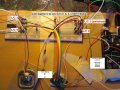
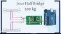
For checking the pipeline I hooked up an arduino mega with a "load scale amp" HX711 and 4 weighing sensors with a max. sensibility of 50kg as I show in picture_1_200kg. Somehow I just got two sensors to work with the "two half bridge". With the four half bridge I recieved no signal.

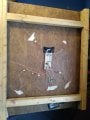
In picture_2_sensor you can see how I installed the sensor. It turned out that its quiet challenging for me to make a good construction for balancing all the sensors.

So I´m thinking about using ready made scales and putting a think stable plate on it. To reach the full capacity I need to use 6 of eg. those:

https://www.amazon.de/Accuweight-AW...coding=UTF8&psc=1&refRID=RPM7BNXXP5RH3HW22CXK

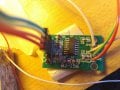
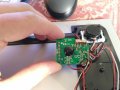
I bought one and opened it up and in comparison to the circuit I had with the hx711, in the ready-made-scale is every pin of the sensor directly connected to the amp. they dont share their connections as in the "two or four half bridge". (picture_3_readymadescale).

How could I weigh with 6 of that scales?

My next step would be to replace the current "load scale amp" with the hx711. If that works I would start to add scales with a hx711 for each.

Is that a way to go?

Thanks in advance!
 

Attachments

DickCappels

Joined Aug 21, 2008
10,171
(Some text removed for clarity.)

How could I weigh with 6 of that scales?

Thanks in advance!
Assuming that the weighing platform is supported entirely by those six scales and there are no mechanical anomalies (nothing is broken), the sum of the weights registered on all scales will be equal to the weight of the load.
 

AlbertHall

Joined Jun 4, 2014
12,346
Assuming that the weighing platform is supported entirely by those six scales and there are no mechanical anomalies (nothing is broken), the sum of the weights registered on all scales will be equal to the weight of the load.
Also assuming that the load is spread between the sensors such that none of them is overloaded.
 

ericgibbs

Joined Jan 29, 2010
18,848
hi,
It is usual to have all the bridges wired in parallel, one option is this LTS image, the AD623 is a single supply IA amp.
I have assumed a typical L/C of 1k, R1 and R2 provide the other half bridge.

You may require some method of balancing the cells, also a +Vref for the AD623 if you wish to weigh close to zero.

Your 4 cell circuit will never work as you have drawn it.

Which type of amp are you using.?
E
 

Attachments

Thread Starter

TillFly

Joined Oct 26, 2016
69
Hey E,

thank you very much for your time!

What do you mean with balancing the cells? mechanically to spread the weight?


In my first attempt I used the "green chip", which you can see on the "two half bridge.pgn" with the HX711. I didnt find a datasheet of the "green chip" yet, just of the "hx711":(https://cdn.sparkfun.com/datasheets/Sensors/ForceFlex/hx711_english.pdf)

This one is the load cells of the "ready-made-scale": https://www.sparkfun.com/datasheets/Sensors/loadsensor.pdf


How would the 4 cell circuit work?


If I understand correctly your LTS image shows a serial approach. What do I need to check to know how many scales I could put in series?

If I follow a parallel approach I need more several amps I guess...?
One advantage of that would be that I then can also stream several inputs to the microcontroller and to the computer. I would prefer this pipeline.

I have also this amp: http://www.ti.com/lit/ds/symlink/ina125.pdf

I will try now to connect to the "ready-made-scale".

Best,
Till
 

ericgibbs

Joined Jan 29, 2010
18,848
hi T,
It is parallel approach for connecting the 4 half bridges.
R1 and R2 are to provide a Vsup/2 centre voltage for the Ad623
What do you mean with balancing the cells? mechanically to spread the weight?
Usually if you were making a load cell platform/base, it would be made of steel so that it would not bend under a weight load.
This means all the weight would be carried equally by the load cells and so give an accurate weight.

Some 4 L/C bases use a balancing PCB, its basically has a pot for each L/C that can be adjusted to balance each bridge.

As a comparison to the AD623's which I normally use, I made a simple project build sometime ago using a HX711 module, it worked OK.

Eric
I will look at your links.

EDIT:
Check this link for the INA125
https://forum.allaboutcircuits.com/...o-project-not-understanding-load-cell.132660/
 

Attachments

Last edited:

Thread Starter

TillFly

Joined Oct 26, 2016
69
Hey Eric,

your pdf "load_cell_cabling_wiring" is about 4-wire or 6-wire load cells. I have the 3-wire bathroom load cells and dont know how I can apply those routings.

In your first LTS image are two halfbridges right?
Each consists of two 3-wire load cells. The top one would be R5(variable) / R6(constant) and R7(variable) / R8 ( constant).

Is this a way to connect four 3-wire load cell in one circuit?
 

Thread Starter

TillFly

Joined Oct 26, 2016
69
At the moment Im struggling to get a constant output of the load cells.
I´m testing a halfbridge with different combinations of four load cells.

Depending on which load cells I use in combination the range of sensor values changes by 100%.

The load cells also seem two have different sensitivity... With more or less the same force the sensor values change different.


Another observation which really confuses me:

I have the sensor pin of Load Cell 1 connected to A+ of the hx711 amp module.
I have the sensor pin of Load Cell 2 connected to A- of the hx711 amp module.

Force on Load Cell 1 connected to A+ causes nothing.
Force on Load Cell 2 connected to A- causes 100000.

Now I switch the connections from the loadcells to A+ and A-.
Then not only the polarity changes but also the sensor range.

Force on Load Cell 1 connected to A- causes change of 50000.
Force on Load Cell 2 connected to A+ causes 50000.

Is the a logic behind this or are the load cells damaged?
 

ericgibbs

Joined Jan 29, 2010
18,848
hi T,
Post #4, shows how to connect them.
Try this, use two 0.01% tolerance resistors, say both 1K or 10K.
This will make the passive other half of a bridge, connect one of your load cells across the resistors.
Measure the voltage between the resistors and the L/C output, do this in turn for all four of your L/C's.
Post your measurements.

E
 

Attachments

Thread Starter

TillFly

Joined Oct 26, 2016
69
I just have 10k 1% resistors at the moment.

The Excitation Voltage with the hx711 module is not 5V. I measured 3,91V.

Then I measure 1942 mV between the resistors.
and 1950 mV between all the L/C outputs.
 
Last edited:

Thread Starter

TillFly

Joined Oct 26, 2016
69
Post #4, shows how to connect them.
E
I got it working!
I´m getting comprehensible changing values from all the L/Cs now.
But what I dont understand yet is how the A+ A- pins with four cells work.

Two L/Cs are routed to the A+ and the other two are going to the A-. Thus two sensors are increasing the sensor value and two are decreasing.
If I put all four L/Cs on the A+ there´s no change at all.

How do I have to route the Cells that there are all affecting in the same direction?
 

ericgibbs

Joined Jan 29, 2010
18,848
Two L/Cs are routed to the A+ and the other two are going to the A-. Thus two sensors are increasing the sensor value and two are decreasing.
If I put all four L/Cs on the A+ there´s no change at all.
hi T,
On the two sensors which are decreasing, reverse the Vext connections, this should give you an increasing output.
If it does, then connect all the L/C's in parallel.
E
EDIT:

The Excitation Voltage with the hx711 module is not 5V. I measured 3,91V.
How s VFB connected.?
 

Attachments

Thread Starter

TillFly

Joined Oct 26, 2016
69
>>reverse the Vext connections
I already tried that with both L/Cs and it didnt change.
Now I just switched the Vext at one and now all the L/C sensor data are increasing.

The cause might be in the hx711 module i´m using. I dont know whats exactly happening there. Pic is attached
There´s also the difference that most amps just go with one wire to a microcontrollers input. With that module there are two SCK and DT.

>>How s VFB connected.?
I dont know how the VFB is connected. Just measured with the multimeter at the excitation wire of the loadcells.


I think I´m already routing in parallel. Is the picture comprehensible?
 

Attachments

ericgibbs

Joined Jan 29, 2010
18,848
hi,
The pictures are OK.
The VFB should be connected to 0V, I will look at my HX711 PCB and see how it is connected.
Are you going to do a simple weight calibration check.?
 

Thread Starter

TillFly

Joined Oct 26, 2016
69
Are you going to do a simple weight calibration check.?
The scale is calibrated now and it works with +- 2 kilogramm. Nice milestone for me, thank you a lot!! :)

My final target is as I explained, to build a weight with the capacity of thousand kilogramm.
The weighing plane will be round with a radius of 85cm.
The six scales shall be positioned in a pentagon and one in the middle.

thoughts..:

>> standby mode
For this setup this hx711 module is with 3€ quiet cheap. Better than the ina125p with 15€
But lets imagine that thing would be running 6 hours. would it be good to have a sleeping mode like the ina125 has?

Furthermore I want to hook up the six weighing scales to an Arduino via twelve AnalogIns and stream the six scaling sensors via serial to my software enviroment of trust.

Is there something I should check out first?
e.g.:
Length of the wires will be maximum 85 cm. Is that ok?
Do I have to compensate the difference in wire length due to resistance?

Best and thanks alot Eric Gibbs!
 

ericgibbs

Joined Jan 29, 2010
18,848
My final target is as I explained, to build a weight with the capacity of thousand kilogramm.
The weighing plane will be round with a radius of 85cm.
The six scales shall be positioned in a pentagon and one in the middle.
hi T,
A metric ton is heavy mass, your scale Base/Platform should be strong enough not to deform under that weight, as that would result in inaccurate weighing.
Obviously don't let the scale operator 'drop' the mass on the platform.
Check the L/C documentation for the 'L/C creep' specification, this could be a problem if say a metric ton was left on the platform for a few hours.


In your program you should have the routines that enable the operator to Zero the scale and if required a Tare Off option.
E

For this setup this hx711 module is with 3€ quiet cheap. Better than the ina125p with 15€
But lets imagine that thing would be running 6 hours. would it be good to have a sleeping mode like the ina125 has?
The equipment should be capable of operating 24/7, personally I would not consider a sleep mode, unless power usage is a concern.

Furthermore I want to hook up the six weighing scales to an Arduino via twelve AnalogIns and stream the six scaling sensors via serial to my software enviroment of trust.
I guess you will be powering the scales from their own supplies, not from the Arduino.
When using multiple power sources for peripherals take care in the commons/grounding connections and the power On/Off sequence.


Is there something I should check out first?
e.g.:
Length of the wires will be maximum 85 cm. Is that ok?
That should be OK, if you operate in a 'electrically noisy' environment, you could screen those wires.

Do I have to compensate the difference in wire length due to resistance?
Not for such short cables.
You will read in load cell documentation, 'do NOT shorten the factory cable lengths', so use the existing wire length where possible.
 

Thread Starter

TillFly

Joined Oct 26, 2016
69
Check the L/C documentation for the 'L/C creep' specification, this could be a problem if say a metric ton was left on the platform for a few hours.
E
L/C Creep specification is (3min)%FS 0.03

I power everything from the arduino so far, but I dont have all the load scales yet. I want to order them this week.
Is it problematic to power everything from the arduino?

Do I have to take care if I make the cables longer? The resistance will increase slightly I guess.
 

ericgibbs

Joined Jan 29, 2010
18,848
L/C Creep specification is (3min)%FS 0.03
I power everything from the arduino so far, but I dont have all the load scales yet. I want to order them this week.
Is it problematic to power everything from the arduino?
Do I have to take care if I make the cables longer? The resistance will increase slightly I guess.

hi T,
I would not power all the L/C's etc from the Arduino, the connectors on the Arduino are only a push fit.
Where possible use soldered joints on the cells and especially on any ground lines.

If you have to lengthen the L/C wires, keep the signal wires the same lengths and as short as possible on a sensor.

E
 

Thread Starter

TillFly

Joined Oct 26, 2016
69
If you have to lengthen the L/C wires, keep the signal wires the same lengths and as short as possible on a sensor.

E
Hi E,
Is the signal wire the total wire track from the sensor to the arduino? So does it make sense to keep the wire from sensor to amp as short as possible and extend from the amp to the mc as needed?

Concerning the power supply:
The load scales are powered with a 3V battery. Could I take a 9V battery block, divide the voltage to 3V and distribute it to the six load scales?
The 3V battery chip (CR2032) has 225mAh
a typical 9V block 550mAh. How long would the battery last?
 
Last edited:

ericgibbs

Joined Jan 29, 2010
18,848
hi T,
I am assuming that your Arduino is being powered by either a 5v from a USB or the onboard 5V reg with say a 9V DC source.?? [battery?]
The L/C is a nominal 1K load resistance, so 5 in parallel would be a 200R load, at say 5V, that is 25mA
The HX bypass transistor will be OK for this current level.

The HX711 will also accept a 5V power source, taking approx 1.5mA for its internal circuitry.

I would recommend that you power all the above devices with the 5V from the Arduino.
Are there any other modules in the project.??

Do you follow OK.

E
 
Top