Facebook
 Google
 GitHub
 Linkedin
Hi all,
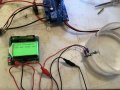
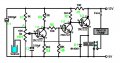
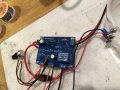
I have built a water level feed control for an electrolyser using the attached circuit but it doesn't quite work as I would like it to.
The sensor consists of two Allen screws in the side of the electrolyser body (test rig) acting as the sensor and when the water level falls below the top screw the motor starts up as expected. However, when the water level rises back to the top screw the motor doesn't switch off.
There is a 10k pot in the circuit that doesn't seem to make any difference to how the device works and what I'm asking is how can I make the motor stop immediately once the water (0.05M KOH) rises to the top screw.
I'm thinking that perhaps the 330uF cap is holding the base of the first transistor on for too long? So maybe a smaller value like 50uF or a 1k bleed resistor across it?
Thoughts appreciated.
Jules
Attachments
-
 178.3 KB Views: 65
 -
 2.5 MB Views: 55