I see the relay coil on/off voltages are not great. Songle SRD-12VDC relay will stay pulled in down to 1.2V and I played around with the circuit and it's not flexible at all.
To fix, I changed the relay transistor to PNP and moved the hysteresis up one stage and the circuit works much better, although still yucky IMHO because the sensing is not ideal, I think not going to work with OP's small carriage bolt vs a rod or plate electrode.
edit: I just realized the electrodes are in the presence of hydrogen gas so you would need an IS barrier. Something to keep voltage/current/capacitance below the ignition limits of IEC 60079. I've played with hydrogen and the smallest spark makes it go boom. It's not difficult to limit the energy available, for explosion safety.
I would ditch OP's circuit completely and go to an AC excitation/sensor system, these are far better.
I’m trying to make OxyHydrogen gas for brazing/welding so some lag in the pump switch off is ok but, as an exercise in effective circuitry, I would like to know how it could be made to work even if in the end I move to a float based method.
I think there’s a pun in there and you are probably right. Another circuit that doesn’t quite make the grade . Time to move away from the thrill seekers.
You have to decide either to salvage and modify the board you have, or build something else.
I think it's a fair bit of work to modify the board you have. It needs a different (PNP) transistor and resistors moved. Even then, the electrode will be sensitive to electrical noise between the main (gas) power supply interacting with the pump power supply, which is just another hassle. Or change to a plastic float switch.
I would change to a circuit using AC excitation, which will work with an electrode or float switch, and not have the spark hazard. I don't know if this is something you are interested in.
There are $4 level controller kits out there as well, but I think most are missing a time-delay to filter out splashing and sloshing.
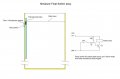
I think it would be better with two reed switches - one at the highest level, and one at the lowest level you want. These switches operate a set/reset bistable of some sort which maintains the pump state until the other switch becomes active. Some thing like the circuit below. As shown this is for pumping down to a level but you want to pump up to a level so swap the 'upper' and 'lower' labels but the (n.c.) stays where it is.
A gate-protected MOSFET like 2N7002K would work too.
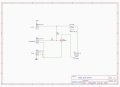
When the reed switch is closed, the BJT transistor will not shut off with those resistor values. There is still base-current flowing to 0.7-1V. The 1k needs to be below 470 ohms, and I would add a 1k to the base for coverage if the wiring shorts to power.
There is a problem - the pump goes on if the magnet is below the reed switch, and off when the magnet is at it or just above. What happens is it just short cycles between between full and not full. The pump goes on/off/on/off/on etc. especially with waves. This is why people go to a two float switch/two electrode system.
Another fix is using a time delay to prevent chattering of the relay/pump from sloshing and waves. To keep the pump off for many seconds after it's low. Does this make sense?
With that circuit, the fluid level will hover between two levels, and the difference between them is the height of the magnet. Generally speaking, a pump will have better long-term reliability if it runs once for one minute rather than 10 times for six seconds each. As above, a more traditional approach is to have two sensors driving a flipflop (solid state, relays, whatever), one at the low level that turns on the pump, and one at a high level that turns off the pump. You could add two sensors below and above the main ones, and combine them into an alarm of some kind to indicate pump problems.
Thanks for all your suggestions. For reasons of space I would prefer just one reed switch. The conductance/studs method was well suited to my Electrolyser design but I can still fit a small float tube inside.
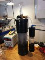
While I expect some frothing I’m not expecting much sloshing of the fluid as it’s a static rig. (see pic) If the switch hysteresis meant that there was a fluid level difference of say 2-3mm that would be fine. Better for it not to go above plates than to go down a bit.
In practice I would slide the reed switch up and down to find the optimum position for acceptable levels.
As I have quite a few IRF840s, would that do for Q1 and with my current R values?
You should have a reverse diode across the pump to protect the MOSFET.
If the switch gets accidentally disconnected then the pump will run continuously.
To avoid that I would have R2 connected from gate to GND and connect the switch between gate and VCC. If the switch gets disconnected now the pump will stop.
I was trying to follow the rules and use the appropriate space. Seems some people think they know what I need better than me.
I’be happy to bring it back here.
I’m just trying to find a cheap way to build a power supply capable to delivering 12V at 10A with some adjustments of I and V to maintain them. I’ll post it a bit later
 Facebook
 Google
 GitHub
 Linkedin
 . Time to move away from the thrill seekers.