Washing machine dead with no power

Thread Starter

jaisunny

Joined Mar 20, 2019
11
Hi guys, found this forum through google. Looks awesome.

Im a complete and utter n00b, but I do own a multimeter. So bare with me, and if possible, dumb things down for me to understand..haha.

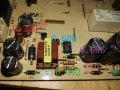
So my washing machine died, and, me being me, I wanted to see if we could repair it.

The machine has 2 boards, and theres power going to both boards. So we don't have a loom issue here I don't think.

I've done some tests with components still mounted to the boards (im not sure if this gives a true reading). But here goes...

Could anyone clarify my findings?

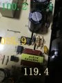
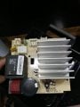
Also attached the other board, which I thought was the bad one, since it has the transformer on..etc
 

Attachments

wayneh

Joined Sep 9, 2010
18,096
Do you see any fuses? There's almost certainly one in there somewhere. You've measured power at the boards, so I guess we know it's plugged in to a live circuit. :p (Seriously, it has to be asked.)

Does your washing machine do anything, or act as if there's no power at all?
 

Thread Starter

jaisunny

Joined Mar 20, 2019
11
Sorry "bear" haha.

I had a "engineer" out who said there is power going to both boards. I also tested it before he came, the loom, to the boards for continuity. They were OK.

Washing machine does nothing at all, it is stone cold dead.

One diode is clearly bad, the 0.002v one. I've removed it just now from the pcb and again, it reads 0.002. So i will change that. But surely that can't be the reason it is totally dead?

I don't see any fuses on either board.
 

wayneh

Joined Sep 9, 2010
18,096
One diode is clearly bad, the 0.002v one. I've removed it just now from the pcb and again, it reads 0.002. So i will change that. But surely that can't be the reason it is totally dead?
Oh that's plenty a reason for a dead appliance. And don't call me Shirley.

If you're lucky, the diode didn't take other parts down with it and didn't fail because of a failure elsewhere. Fingers crossed.
 

Thread Starter

jaisunny

Joined Mar 20, 2019
11
Oh that's plenty a reason for a dead appliance. And don't call me Shirley.

If you're lucky, the diode didn't take other parts down with it and didn't fail because of a failure elsewhere. Fingers crossed.
Thanks, I guess i'll order a diode up and go from there.

There's no way to test a cap while mounted is there? with just a mulitmeter?

One other thing, when i google the details of the diode "SR110 649Y" nothing comes up. Not even on ebay apart from one seller in Germany. Do you think I could go for a SR120? or kindly point me in the direction of a alternative..
 

wayneh

Joined Sep 9, 2010
18,096
There's no way to test a cap while mounted is there? with just a mulitmeter?.
No, not really. There is such a thing as an ESR test that can be done on board, but few of us have the test equipment. I used to cringe when people recommended just replacing all the electrolytic caps but I'm more of a believer now. If you can't find a schematic or have nothing obvious to try, I'd say go ahead and try it. Those caps do age, so putting in new ones extends the life of the board even if the cap wasn't the root problem. And a failed capacitor is a frequent cause of board failure.
One other thing, when i google the details of the diode "SR110 649Y" nothing comes up. Not even on ebay apart from one seller in Germany. Do you think I could go for a SR120? or kindly point me in the direction of a alternative..
You don't need an exact replacement, if you can't find an SR110. Just be sure to meet or exceed the ratings, ie. it needs to be at least 1A, 100V Schottky barrier diode. But they're in stock at Mouser.
 

Thread Starter

jaisunny

Joined Mar 20, 2019
11
No, not really. There is such a thing as an ESR test that can be done on board, but few of us have the test equipment. I used to cringe when people recommended just replacing all the electrolytic caps but I'm more of a believer now. If you can't find a schematic or have nothing obvious to try, I'd say go ahead and try it. Those caps do age, so putting in new ones extends the life of the board even if the cap wasn't the root problem. And a failed capacitor is a frequent cause of board failure.

You don't need an exact replacement, if you can't find an SR110. Just be sure to meet or exceed the ratings, ie. it needs to be at least 1A, 100V Schottky barrier diode. But they're in stock at Mouser.
SR1100 is the same as SR110?
 

Thread Starter

jaisunny

Joined Mar 20, 2019
11
First things first. Do I see anywhere where you stated the Make and Model of the machine?
Im not sure it'll make any kind of difference, but its a BEKO WDX8543130W. I found someone online searching for the schematics of the boards but with no success. So I think it isn't easily obtainable.

Hire a professional. Playing with line voltages by the unskilled can get you killed.
I've done plenty of soldering, confident with that. And the boards have been removed for about 2 months now, the caps discharged using a discharge tool. So its pretty much dead. I don't fiddle with live boards.

Besides, i've already gone down the route of a "professional" they wanted near the same price of a brand new pcb board to look at it. And a brand new PCB board is almost the same price as the entire machine. So its pretty much pointless.

So its either
1-scrap it
2-DIY
 

wayneh

Joined Sep 9, 2010
18,096
I am probably wrong, but I just assumed SR110 = 10v and SR1100 is 100v.

There seems to be lots of SR1100 floating around, but not SR110 in the UK (mouser is OOS for uk residents)
I haven't seen a SR1100, but the SR110 is a 100V, 1A Schottky diode. Don't make assumptions - read the number off the part.
 

SLK001

Joined Nov 29, 2011
1,549
One diode is clearly bad, the 0.002v one... But surely that can't be the reason it is totally dead?
It can be. A lot of the SMPS ICs have a "good power" pin. If there isn't "good power", the device doesn't turn on. I see that for TVs quite a lot.

To get a UL rating, the line in HAS to have a fuseable link somewhere. Find it and check for continuety.
 

LesJones

Joined Jan 8, 2017
4,511
The left hand side of the larger board looks like a switch mode power supply. I am guessing that the two pin connector in the bottom left hand corner is the AC input to the board. Can you confirm that this is the case ? (Your pictures are not sharp enough to read all the labels.)
If my guess is correct can you test for continuity between the live and neutral on the mains plug to the two pins on the connector that plugs into this connector ? (This is to find out if this part of the board has power applied to it all of the time without you having to take readings of high voltages.)
I suspect that the small board with the large heat sink could be the power supply for the control electronics. What is under the large heat sink on this board ? (It looks too large to be for a linear regulator considering the size of the transformer.) Pictures of the etch side of the boards would also be helpful.

Les.
 
Top