Want to make a 4 bit counter using flip flops

Thread Starter

power waleed

Joined Feb 16, 2019
18
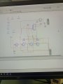
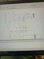
Hi to make it simple, I have created a 4 bit counter and i want it to count till decimal number number 9(=1001) and then stop the clock when it reaches that decimal number 9.

So can anyone help me with it.

my circuit diagram is below which I've drawn so far.
 

Attachments

dl324

Joined Mar 30, 2015
16,846
Welcome to AAC!

Can you read the image you posted?
upload_2019-2-16_9-14-18.png

It looks like you're using MultiSim. Post a clipped screen capture or print to PDF in black and white.

Is this school work?
 

dl324

Joined Mar 30, 2015
16,846
okay

is this one clear
That's only marginally better. Your schematic drawing style is atrocious. Post your truth tables so we don't have to try to follow your messy routing.

BTW, if you use the shift key, you can force MultiSim to make cleaner routes. In any case, you can always clean up the wires after they're placed. Neatness matters.
 

Thread Starter

power waleed

Joined Feb 16, 2019
18
That's only marginally better. Your schematic drawing style is atrocious. Post your truth tables so we don't have to try to follow your messy routing.

BTW, if you use the shift key, you can force MultiSim to make cleaner routes. In any case, you can always clean up the wires after they're placed. Neatness matters.

it's kinda school work. And the file currently is at the Lab so i just had that picture taken. and I dont have the truth tables I was just told to make a circuit
 

Thread Starter

power waleed

Joined Feb 16, 2019
18
Slinging gates isn't the way a counter is usually designed. You must have been taught a formal method for designing a synchronous counter.

yeah below are the screen capture of some of my slides regarding 3 bit synchronous and the multiplexer


and we can use any TTL logic gates in multisim to design our circuit
 

Attachments

Thread Starter

power waleed

Joined Feb 16, 2019
18
this is the question i got

2. Multiplexer* (recommended method!)

  1. Load data into a parallel-in, parallel-out shift register.

  2. A 10 to 1 multiplexer (more likely 16 to 1. Last 6 bits unused) has input 0 connected to logic 0 (start bit), bits 1 to 8 connected to the shift register and bit 9 connected to logic 1 (stop bit). Remaining (spare) bits also connected to logic 1.

  3. Multiplexer output is inverted and level shifted to fit the RS232 format.

  4. To transmit a character, a trigger pulse resets a counter to zero, which then generates the output sequence 0000, 0001, 0010,...,1001, i.e. 0 to 9. It stops counting on 1001, and remains in that state until reset to zero. The counter clock runs at the selected Baudrate, e.g. 9600 Hz.

  5. The counter trigger pulse needs to be synchronous with the main timing clock.

  6. Counter outputs feed the multiplexer Select inputs.
 

Thread Starter

power waleed

Joined Feb 16, 2019
18
What does a 3 bit counter and multiplexer have to do with designing a 4 bit counter?

Post the truth table for the counter you're designing.

I am not given with the truth table thats why. I have to find the truth table and etc thats why i am confused Ok how to do it.

I sent the question thats what i got
 

dl324

Joined Mar 30, 2015
16,846
I am not given with the truth table thats why. I have to find the truth table and etc thats why i am confused Ok how to do it.
That's typically the way it is with school work. You're taught some fundamentals and then asked to practice them so you'll have a better understanding of how they work.

You have this truth table/state table that shows how to implement an octal counter with D flip flops.

upload_2019-2-16_15-7-12.png
What type of flip flop are you supposed to use for your decade counter and do you know how to draw the truth table?
 

Thread Starter

power waleed

Joined Feb 16, 2019
18
That's typically the way it is with school work. You're taught some fundamentals and then asked to practice them so you'll have a better understanding of how they work.

You have this truth table/state table that shows how to implement an octal counter with D flip flops.

View attachment 170311
What type of flip flop are you supposed to use for your decade counter and do you know how to draw the truth table?


This is the half adder circuit below we had to use as a flip flop and the truth table is also given below.

So we had to use 4 of them as a 4 bit counter
 

Attachments

djsfantasi

Joined Apr 11, 2010
9,156
Ok, I don’t get it. I’ve never heard of a half adder used to make a flip flop. I did some checking and there are references to using a flip flop to make a half adder, but not the other way.

The TS is throwing us references which may or may not be applicable to his problem. IMHO, there is a lot more understanding of what s/he’s got before the problem can be solved.

This is not a difficult problem, “making a 4 bit counter using 4 flip flops”. I propose that a simple Google search would supply the answer. I pulled up an answer is 3 seconds.

We’ve seen multiplexers, serial to parallel shift register with flip flops, half adders, truth tables and more. None have anything to do with “making a 4 bit counter with 4 flip flops”

To paraphrase dl324, he’s slinging schematics without understanding them. It’s going to take a lot of work to help someone who as of yet, cannot understand the material.
 

Thread Starter

power waleed

Joined Feb 16, 2019
18
Ok, I don’t get it. I’ve never heard of a half adder used to make a flip flop. I did some checking and there are references to using a flip flop to make a half adder, but not the other way.

The TS is throwing us references which may or may not be applicable to his problem. IMHO, there is a lot more understanding of what s/he’s got before the problem can be solved.

This is not a difficult problem, “making a 4 bit counter using 4 flip flops”. I propose that a simple Google search would supply the answer. I pulled up an answer is 3 seconds.

We’ve seen multiplexers, serial to parallel shift register with flip flops, half adders, truth tables and more. None have anything to do with “making a 4 bit counter with 4 flip flops”

To paraphrase dl324, he’s slinging schematics without understanding them. It’s going to take a lot of work to help someone who as of yet, cannot understand the material.

I have the source file for the multisim and i can send u that if you provide me with ur email. And could u edit and send me.
 

djsfantasi

Joined Apr 11, 2010
9,156
I don’t get it how to do can u do that on my circuit diagram
I’m to tired to review your circuit diagram. My only comment is that perhaps you need to look outside the box. Perhaps your circuit diagram is wrong and you need to start over.

If I’ve made a cake and it doesn’t look or taste like a cake, maybe I need a new recipe. Just sayin’
 

Thread Starter

power waleed

Joined Feb 16, 2019
18
I’m to tired to review your circuit diagram. My only comment is that perhaps you need to look outside the box. Perhaps your circuit diagram is wrong and you need to start over.

If I’ve made a cake and it doesn’t look or taste like a cake, maybe I need a new recipe. Just sayin’
My circuit diagram is correct and its just i have to connect in a proper way so it stops when it reaches decimal number 9
 
Top