Voltage to Frequency Design

Thread Starter

Pedro Garcia 1

Joined Dec 5, 2017
2
Hello, this is my first time posting on this website, but I am desperate for knowledge and help.

My electronics professor wants me to create a voltage to frequency converter. the specs are straight forward. The control voltage (DC)needs to be from 0V-10V. The output (square waveform) needs to be from 0V-7V and its frequency has to be proportional in such a way that for every volt inputted, 1KHz is outputted, etc. The duty cycle is not important for this design. It can also output a 0V-7V triangular waveform but that is optional. I have looked into various designs and I found two that seem practical.
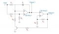
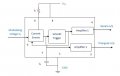
The first one is just an op-amp integrator configuration with a schmit trigger. What I understand is that the op-amp gives me a triangular wave and the schmitt gives me the square wave (a question that arises for me is, how do I determine the values of the components?). And the other is more confusing for me. It contains a current source ( I am confused with this circuit), the schmitt trigger and two op amps which output the respective triangular and square wave. Does anyone have some idea or advice on how I should start? thanks !!
 

Attachments

WBahn

Joined Mar 31, 2012
32,823
How you select components would be to analyze the circuit to see how it behaves and how the component values influence that behavior. Then you are in a position to select component values that meet your specifications (assuming that they CAN be met).

What is it about the current source that is confusing you? Assuming you have a black box labeled "current source", do you understand how the circuit achieves voltage-to-frequency conversion?
 

sjgallagher2

Joined Feb 6, 2013
131
Something that may not be obvious is that a capacitor, when charged with constant voltage, will have its voltage ramp up exponentially. But when charged with a constant current, a capacitor voltage charges up linearly, a ramp of constant slope. This can be interpreted different ways depending on your familiarity with capacitors. From a mathematics standpoint, capacitors follow the rule of I = dV/dt i.e. capacitors resist changes in voltage. So with a constant current source, dV/dt (the slope) is constant. So when you supply a capacitor with constant current, the voltage across the capacitor will ramp up linearly. This should help you understand the mechanism behind the second circuit.

For design, design based on the requirements such as dynamic range (0-10V), slope (1kHz/V), minimum and maximum frequencies (not specified), output waveform voltage (0-7V) and linearity/distortion and temperature stability, which are very important but probably not considered here. (For what it's worth: To analyze circuits for temperature stability, explicitly state the temperature-dependence of components, especially semiconductors, after determining their effect on the circuit). Let me say that while it may seem obvious, you can't easily make a V/F converter which goes to zero frequency (DC) so I would start at say, 1kHz for 0V. Other than that, this is a good design exercise, so have at it.
 

DickCappels

Joined Aug 21, 2008
10,661
I think sjgallagher2 mistyped " Something that may not be obvious is that a capacitor, when charged with constant voltage will have its voltage ramp up exponentially."

I think he meant to write " Something that may not be obvious is that a capacitor, when charged with constant current will have its voltage ramp up linearly."

volts/second = current/capacitance

One volt per second appears across a 1 farad capacitor being charged with one amp.
 

WBahn

Joined Mar 31, 2012
32,823
I think he was saying what he meant, but there is an assumed element he didn't mention.

When you charge with a constant voltage (via a series resistor), the capacitor voltage will ramp exponentially (although I don't think that is the correct description -- probably something more like exponentially asymptotic, but the idea is close enough). When you charge with a constant current, then the capacitor voltage will ramp linearly.
 

sjgallagher2

Joined Feb 6, 2013
131
Yes technically the charging curve is a 1 - e^(-x) function! Calling it exponential is a bit confusing but I didn't have a better word for it. I figure most folks here have an idea of the charging curve of a cap at constant voltage in any case. Anyway, I did mean the two statements to be taken together. I.e. "Something that may not be obvious is that a capacitor, when charged with constant voltage, will have its voltage ramp up exponentially; but when charged with a constant current, a capacitor voltage charges up linearly, a ramp of constant slope." I could have phrased it better but hopefully the point is clear enough.
 
Top