Voltage sign confusion

Thread Starter

abhiananth

Joined Jul 24, 2014
18
Hi,

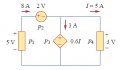
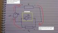
I crossed this circuit while solving the problems.


Fig: circuit

As per my knowledge, the positive and negative sign of the voltage of an element P4 marked in it is wrong.


Fig: direction circuit – wrong

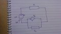
My learnings on signs of the voltage of the elements is as follow:

1. Voltage comes out of positive terminal of the source

2. Voltage drop occurs from positive terminal to negative terminal of the elements.

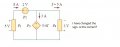
Re-drawing the above circuit by providing sign only for source voltage


Fig: Re-draw circuit – source sign

Now, I am assigning sign for the elements based on the source voltage sign


Fig: Re-draw circuit – all sign

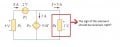
So, reversing the sign of the element P4


Fig: direction circuit - right

Note: If images are not visible, i have uploaded. Please refer to it based on the respective name i have given below each image

My questions are:[

What I have mentioned is correct or not?

If not, please correct me.
 

Attachments

Thread Starter

abhiananth

Joined Jul 24, 2014
18
Sorry for late reply. Wifi in my laptop is not working. So, I am not able to access the internet.

@MikeML Thanks for your reply.

I have read the thread that you shared.

That thread talks about what will happen if we have 2 voltage sources connected to each other with same terminals (if opposite terminals were connected voltage will built up) via elements(resistors)

My thread is regarding voltage sign (potential drop from one terminal of an element to other terminal of the same element not current direction) of each elements in the circuit with both independent and dependent voltage sources.

Its my mistake that I wrote ‘independent voltage source’ instead of ‘dependent voltage source’ in the diagram ‘Re-draw circuit – all sign’.

Here is edited diagram
Re-draw circuit – all sign(edited).jpg

P3 is dependent voltage source (marked with yellow square)
 

studiot

Joined Nov 9, 2007
4,998
There is no such thing as voltage flow direction.

You need to get the basics straightened out before tackling dependent sources.

I don't see a correctly identified dependent source in your diagram.
Just calling it dependent doesn't count.
What do you understand a dependent source to mean?

Hint dependent upon what?????????
 
Last edited:

wayneh

Joined Sep 9, 2010
18,108
I cannot understand what you are asking. What are P1, P2, and P4 and what is a "dependent voltage source"?

All voltage measurements are relative to a reference. It is customary to cite voltages relative to either the lowest voltage of a circuit, so that all voltages are positive, or against a "common" such as when there is a positive rail and a negative rail on either side of common.

The voltage ∆V across a component depends on the current flowing through it.
 

Thread Starter

abhiananth

Joined Jul 24, 2014
18
I am asking about the voltage representation of the element P4.

P1 and P4 are any elements (e.g.: resistors)

P2 – independent voltage source

P4 – dependent voltage source

I haven’t read much about dependent voltage source. Based on the diagonal sign, I am saying its dependent voltage source

I am learning circuit theory by self-reading. In that they talk about voltage representation.

voltage representation - book circuit.jpg

In that book they gave one problem for finding voltage and current.

circuit.jpg

As @wayneh said, ‘All voltage measurements are relative to a reference’.

Here I took P2(source) as reference

I am assigning letter to the terminal of the elements for clarity.

Re-draw circuit – terminals.jpg

P2 is source. So, its providing voltage.

For P1, voltage drop occurs from point a to b.

Re-draw circuit – terminals - P1.jpg

I am not sure about P3 since it is a dependent voltage source. I don’t know much about it.

In book, for P4, the voltage drop occurs from f to e. but as far my understanding it should be from e to f.

circuit.jpg Re-draw circuit – terminals - P4.jpg

My question is about whether I am correct that the voltage drop occurs from e to f?

Or if not, please correct me.
 

studiot

Joined Nov 9, 2007
4,998
I'm sorry but I can't help you if you don't cooperate.

Cooperation means answering the couple of simple, civil questions I asked to find out if soneone needs to explain what a dependent voltage source is.

But It is seriously concerning when you seem to misunderstand something even more basic, the question of what is voltage, and ignore helpful comments about that.

So let us start at the beginning what is voltage?


What do you mena by voltage flow direction?

What do you understand a dependent source to mean?

A short (one or two lines) is plenty for us to pick up how to answer.
 

Thread Starter

abhiananth

Joined Jul 24, 2014
18
Thanks for your reply studiot.

This is my understanding about the questions you asked

voltage is the potential difference that occurs between two points

voltage flow direction in the sense, i mentioned that voltage drop occurs from one point to other point

independent voltage source means, the source will provide the necessary current to maintain the constant voltage

dependent voltage source means, we can vary the voltage as per our requirement and the source will provide the necessary current to maintain the voltage. usually the voltage is varied by another circuit
 

studiot

Joined Nov 9, 2007
4,998
OK

There are two separate and distinct quantities that are measured in volts and you nearly have the right of it.

Firstly potential.
This is a (single) point function where we can assign a potential to any (and every) point in a particular region of space, for example in the space between the plates of a capacitor.
Note that potential cannot apply to two or more points, only one at a time.

Secondly Potential Difference or PD (often called potential drop, but that is unofficial)

PD is the difference between the potential at two points in space or a circuit (usually two nodes), so is not a point function, but requires two points.

Since the potential at both points is measured in volts, the difference also has the units or dimensions of volts.

PD is the quantity that is normally of interest to circuit engineers and is often shortened to 'voltage' or volts etc.

If you look at my diagram B this is the normal way to represent sources and sinks in circuits, but you will find both.


I repeat that there is no such quantity as voltage flow direction. Voltage does not 'flow'.
This is important to understand.

You need to get a firm grasp of this because we have conventions to show the direction of current flow and how we count potential difference.

The convention is :-
PD is counted positive in the direction from negative to positve

Current flow is counted positive in the direction from positive to negative

Yes that's right the other way round!

This is known as the sink or motor convention and is the one you are using, and is usually known as 'the conventional current convention'

souceconv.jpg

Diagram A shows a power source.

A potential rise through the element is in a sense to drive the current in the same sense.
If the senses of voltage and current are taken as positive a product of VI represents the device acting as a source of power ie a generator.
If there is a reversal of V or I then the product will be negative corresponding to an absorbtion of power by the device or circuit .
The device or circuit is then a negative source, usually called a sink or motor.

The motor or sink conventions shown in B are the converse.

Taking the directions or senses indicated a positive product indicates a positive sink or consumer of power or a motor.
A negative V or I would result in a negative product VI indicating the device is a negative sink ie a positive source or generator.

That's alot to chew on, see how you get on.
 

Thread Starter

abhiananth

Joined Jul 24, 2014
18
Hi studio.

These are my learnings from your previous post.

There are only two things in circuits. Source and sink

In source, the current flows in the direction as potential rise. i.e. the current comes out of the positive terminal. That means the power value will be positive meaning that it is giving power

In sink, the current flows in the direction as potential drop. i.e. the current comes out of the negative terminal. That means the power value will be negative meaning that it is absorbing power

I understood all the things you mentioned. These last two lines confused me.

Taking the directions or senses indicated a positive product indicates a positive sink or consumer of power or a motor.
A negative V or I would result in a negative product VI indicating the device is a negative sink ie a positive source or generator.
It looks like it contradicts with what u said in previous lines.

Based on the learnings I come up with this analysis.

1 source and 1 sink
1 source and 1 sink.jpg

1 source and many sinks
1 source and many sink.jpg

sources and sinks in my problem circuit
source and sink - problem circuit.jpg


But in book, they gave circuit like this. In that, the element P4 is sink. But it looks like source as the current goes in the negative terminal.
circuit.jpg
 

studiot

Joined Nov 9, 2007
4,998
There is no contradiction.

What I said was that there are two conventions.

I have shown them at A and B.

A is called the Generator or Source convention

B is called the Motor or Sink convention.

You only use one or the other at a time. Not both.

Whatever you do, don't use one convention for sources and the other for sinks, that is a recipe for disaster.

If you like, in A sources are positive, sinks are negative.
In B sources are negative, sinks are positive.

Because there are two conventions it is important to know which the author of a book is using, especially when you come to dependent sources.

You were quite correct in your earlier definition of an independent source.
It maintains the stated conditions, regardless of the external circuit connected.

There are two types of independent source or sink.

A ( note ideal) Voltage source or sink, which maintains a specified voltage across its terminals, regardless of the current passing through it.

Can you think of an example of independent source and an independent sink?

Then we can come to dependent sources/sinks and the reason I said that you have not shown a proper one in your original figure.
 
Last edited:

Thread Starter

abhiananth

Joined Jul 24, 2014
18
Independent voltage source - battery

Independent current source - i have seen one power supply in lab. it provides constant 5 amps. not sure how it provides constant 5 amps

Independent sink - resistors
 

studiot

Joined Nov 9, 2007
4,998
I was only talking about voltage sources so yes to the battery, its voltage is independent of the current supplied.

Why do you think that a resistor is an independent sink?

(hint it isn't the voltage across it depends upon the current through it)

We will come to current sources along with dependent sources.
 

Thread Starter

abhiananth

Joined Jul 24, 2014
18
i think resistor is independent sink because it absorbs energy in constant basis

Potentiometer is dependent sink because it absorbs energy and we can vary the the amount it absorbs
 

studiot

Joined Nov 9, 2007
4,998
Neither of these are true statements.

An independent voltage source maintains the voltage across its terminals, regardless of the current taken from it.

A battery is a good example.
The mains wall socket is another.

An independent voltage sink maintains the voltage across its terminals regardless of the current supplied to it.

A Zener diode is a good example.


An independent current source outputs a fixed current, regardless of the voltage impressed across its terminals.

An independent current sink draws a fixed current, regardless of the voltage impressed across its terminals.

Note that one of my examples above referred to alternating voltage.
The idea of voltage or current sources and sinks also applies to alternating current/voltage.
Of course positive and negative have no relevance to AC, except as a direction sign convention.

It is hard to find simple individual devices that act as current sources or sinks.
Current sources or sinks usually contain some combination of devices that collectively adjust the resistance (impedance at AC) to the impressed voltage so that the current is then constant.
 
Last edited:

Thread Starter

abhiananth

Joined Jul 24, 2014
18
thanks studiot.

i think i got it now.

resistor is dependent sink , right?

then voltage divider circuit (which uses resistor to divide voltage) should be dependent voltage source, as it power anoth. am i right?

As you said, we can use either of the convection(your diagram A and B). And how to find which convection the author of the book used in this circuit?
circuit.jpg
 
Top