Facebook
 Google
 GitHub
 Linkedin


Fig1
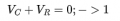
I am bit confused of the arrow direction of Vc and V0. The derivation is as below

I get that -Ve sign which is not available in the answer.
And in equation 2, should it be -V0 or +V0 for 250V initial voltage. Please guide me to write the correct equations.