Voltage regulator and caps getting very hot

Thread Starter

andrei.mita

Joined Jun 19, 2018
25
Hi,

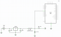
I'm working on reading the value of a pressure sensor. The pressure sensor is a variable resistance between 10-180ohm with a working voltage between 6-24V. I'm using a voltage divider to read the voltage and convert the value to pressure through a polynomial formula.

The sensor is powered by a car battery, but because the voltage fluctuates a lot I had to put a voltage regulator in front of the voltage divider. I'm using a L7808, 8V, 1.5A and 2 x 10uF caps. The second resistor in the voltage divider is 47ohm, 3W. There is also a Zener diode at 4.7V 5W that protects the Arduino input.

The problem I'm facing right now is that the voltage regulator and the caps get very very hot. I knew I had to get a high power rated resistor to use in series and I figured out I also had to use a high power Zener diode. But now the voltage regulator and the 2 caps get incredibly hot. I can't figure out why and I'm also out of ideas on how to fix this.

I believe the voltage regulator and the caps get hot only when the Zener diode lets the current pass through, but I can't test right now because I have to generate a lot of pressure on the sensor to get the resistance up. Is this right? How can this be avoided? Maybe it's stupid, but moving the ground of the zener diode from the caps/voltage regulator will have no effects, right?

Thanks,
Andrei
 

Attachments

jaredwolff

Joined Jul 1, 2017
58
In order to get the 8V the linear regulator sinks the power lost from going from ~12 to 8V as heat. So bear that in mind. You're also sinking about 140 mA into that resistor divider. Not great.

Is there any reason why you wouldn't want to use an off-the-shelf pressure sensing IC? The LPS22HB is a good option and works between 1.7 and 3.6V (so it should work with your Arduino)
 

Thread Starter

andrei.mita

Joined Jun 19, 2018
25
I'm don't have any heat sink at all. I actually discovered a couple of minutes ago that these things exist while reading other posts.

I was also trying to calculate the heat that the voltage regulator needs to dissipate.
 

joeyd999

Joined Jun 6, 2011
5,283
Do you have a link to the datasheet for the pressure sensor?

I suspect you are overthinking/over-complicating the problem.
 

Thread Starter

andrei.mita

Joined Jun 19, 2018
25
In order to get the 8V the linear regulator sinks the power lost from going from ~12 to 8V as heat. So bear that in mind. You're also sinking about 140 mA into that resistor divider. Not great.

Is there any reason why you wouldn't want to use an off-the-shelf pressure sensing IC? The LPS22HB is a good option and works between 1.7 and 3.6V (so it should work with your Arduino)
Unfortunately (for me) the sensor I have to work with is an automotive one. There is no other/better option available.

When the system is fired up, the calculated current is 400mA and drop to 85mA when it reaches the working point (1bar, sensor becomes a 47ohm resistor).

If I'm getting this right, in normal working conditions, the voltage regulator will have to drop 13.4V (alternator on) to 8V at 400mA.
This give me an incredible 2.16W to heat things up.
 

Thread Starter

andrei.mita

Joined Jun 19, 2018
25
Do you have a link to the datasheet for the pressure sensor?

I suspect you are overthinking/over-complicating the problem.
It is a VDO automotive proprietary pressure sensor. The only data I have are the working voltage (6-24V) and the resistance (10-180ohm corresponding to 0-5bar). I managed to get some other reading points in between based on which I managed to compute a polynomial function. That's all I have.

The sensor is usually used with a dashboard clock, but not sure how that one works.
 

joeyd999

Joined Jun 6, 2011
5,283
The only data I have are the working voltage (6-24V) and the resistance (10-180ohm corresponding to 0-5bar).
If it is really a simple resistive sensor, I am suspicious of the low-end of the 6-24V spec. Unless it includes internal active circuitry, there is no reason why it should not operate well below 6V.

If this were my project, I'd consider either:

1) Using the Arduino power to power the divider. Is it 5V? If so -- and you are using a 47 ohm resistor -- max sensor current at 10 Ohms would be 87 mA. Far more reasonable. And if you tie Vref to the same 5V, then the output is ratiometric -- meaning you can ignore reference noise. If the Arduino is 3V, the max current will be 53mA.

2) Drive the sensor with an even smaller constant current source -- say 16 2/3 mA. This will give you 3V FSO -- so you use a 3V reference.

Question for confirmation: Can you measure the resistance of the sensor with an ohmmeter, in both directions?
 

AlbertHall

Joined Jun 4, 2014
12,346
I'm don't have any heat sink at all. I actually discovered a couple of minutes ago that these things exist while reading other posts.

I was also trying to calculate the heat that the voltage regulator needs to dissipate.
In that case it will get hot.
If you're going to get a heatsink for it, it needs to be a conservative maximum 20°C/W
 

LesJones

Joined Jan 8, 2017
4,188
I would suggest that you change the way you are powering the sensor. I suggest using a constant current source of about 27 mA feeding the sensor. The output voltage will then be directly proportional to the sensor resistance. The constant current source could be as simple as an LM317 configured as a constant current source. This is an example of an LM317 used as a constant current source. You would use a 47 ohm resisror in place ofthe 10 ohm resistor in the example. The voltage across the sensor would vary between 0.27 volts (Sensor at 10 ohms.) and 4.86 volts. (Sensor at 180 ohms.)

Les.
 

dl324

Joined Mar 30, 2015
16,909
Welcome to AAC!

Thank you for posting a schematic and using paragraphs to organize your thoughts.

Cropped schematic showing relevant components:
upload_2018-6-19_9-10-21.png

And drawn more conventionally:
upload_2018-6-19_9-37-20.png
The problem I'm facing right now is that the voltage regulator and the caps get very very hot.
You have a power dissipation problem, but the capacitor should not be getting hot unless it's being transferred by radiation from the regulator.

The rheostat will dissipate about 1W max (when set to 10 ohms). If this isn't a high power wirewound rheostat you risk burning it out. Power ratings for variable resistors are for the entire resistance. If you're using 5%, you need to derate the power rating by 95%.

The load resistor will dissipate 0.47W. The regulator will be dissipating almost 2W and should have a heatsink.

The capacitors you're using aren't appropriate. You should have a small value ceramic on the output (if you use one), and the datasheet specifies 0.33uF on the input
 

Thread Starter

andrei.mita

Joined Jun 19, 2018
25
If it is really a simple resistive sensor, I am suspicious of the low-end of the 6-24V spec. Unless it includes internal active circuitry, there is no reason why it should not operate well below 6V.

If this were my project, I'd consider either:

1) Using the Arduino power to power the divider. Is it 5V? If so -- and you are using a 47 ohm resistor -- max sensor current at 10 Ohms would be 87 mA. Far more reasonable. And if you tie Vref to the same 5V, then the output is ratiometric -- meaning you can ignore reference noise. If the Arduino is 3V, the max current will be 53mA.

2) Drive the sensor with an even smaller constant current source -- say 16 2/3 mA. This will give you 3V FSO -- so you use a 3V reference.

Question for confirmation: Can you measure the resistance of the sensor with an ohmmeter, in both directions?
Yes, I am able to measure the resistance both ways, same value.
I have no clue why there is a minimum voltage. That was my first question from day one as indeed it could have been so much easier to just power it from the Arduino. I do have 3 sensors to power thou, this one and 2 other temp sensors with similar specs (except those are NTC).

I'm attaching everything I have found about the sensor.
sensor.PNG
 

Thread Starter

andrei.mita

Joined Jun 19, 2018
25
The load resistor will dissipate 0.47W. The regulator will be dissipating almost 2W and should have a heatsink.

The capacitors you're using aren't appropriate. You should have a small value ceramic on the output (if you use one), and the datasheet specifies 0.33uF on the input
Thanks a lot, Dennis. I will explore both the sink heat option and the constant current source options.

As for the capacitors, I was under the impression the values from the datasheet are minimal and that going bigger is actually better in this case. I admit I have no idea why.

The ripple current of the capacitor is 60mA. Isn't this exceed in my case? Especially when the z diode block the voltage from going above 4.7V?
 

dl324

Joined Mar 30, 2015
16,909
As for the capacitors, I was under the impression the values from the datasheet are minimal and that going bigger is actually better in this case. I admit I have no idea why.
The reason is given in the datasheet. The input capacitor is only required if the regulator is a "long" distance from the voltage source. The output capacitor is optional, and improves transient response.
The ripple current of the capacitor is 60mA. Isn't this exceed in my case? Especially when the z diode block the voltage from going above 4.7V?
Which capacitor has such a large ripple current, and why?
 

bertus

Joined Apr 5, 2008
22,276
Hello,

In your schematic, you have the sensor floating from ground.
In the sensor drawing the housing is supposed to be on ground.
How is your sensor mounted at the moment?

Bertus
 

Thread Starter

andrei.mita

Joined Jun 19, 2018
25
I would suggest that you change the way you are powering the sensor. I suggest using a constant current source of about 27 mA feeding the sensor. The output voltage will then be directly proportional to the sensor resistance. The constant current source could be as simple as an LM317 configured as a constant current source. This is an example of an LM317 used as a constant current source. You would use a 47 ohm resisror in place ofthe 10 ohm resistor in the example. The voltage across the sensor would vary between 0.27 volts (Sensor at 10 ohms.) and 4.86 volts. (Sensor at 180 ohms.)

Les.
Thanks, Les. Both you and Joey suggested to go with a constant current source. I have to research this one, not sure I fully understand how it will work. But it's definitely a great option if it solves the issue.
 

bertus

Joined Apr 5, 2008
22,276
Hello,

With the constant current regulator, the sensor will be grounded.
Here are some more details about the constant current regulator:

LM317_constant_current_regulator.png

Bertus
 

crutschow

Joined Mar 14, 2008
34,408
If the capacitors are getting hot, that would suggest the regulator is oscillating.
Try 0.33μF ceramic caps directly from the input and output pins to its ground pin.

Using a constant-current sounds like a good idea as it converts resistance linearly to voltage, thus making the pressure reading linear.

But you would need a separate constant-current source for each sensor.
 

ebp

Joined Feb 8, 2018
2,332
The voltage rating may be little more than "you can use this in a 6 V, 12 V or 24 V automotive system."

A minimum voltage may be necessary to help assure reliability if there really is a contact that moves over a resistive element.

The ripple current in your capacitors should be very nearly zero. Ripple current occurs in things like filters after rectifiers where energy is constantly being alternately dumped into then removed from a capacitor. The input cap will have a little ripple because the input voltage will vary, but it won't be varying constantly or with any great amplitude or frequency. For practical purposes, the output capacitor will see zero ripple current.

If you don't have an oscilloscope and have meter that reads zero when set to AC and you try to measure a steady DC voltage (any handy battery not connected to some load will do to allow you check this, if you don't know), you can check for oscillation or high ripple voltage by simply measuring the voltage across each cap on the AC range. You would normally expect the AC voltage across the input cap to be some small fraction of a volt when actually in a car with the alternator running. The AC on the output cap should be no more than a few millivolts.
 
Thanks a lot, Dennis. I will explore both the sink heat option and the constant current source options.

As for the capacitors, I was under the impression the values from the datasheet are minimal and that going bigger is actually better in this case. I admit I have no idea why.

The ripple current of the capacitor is 60mA. Isn't this exceed in my case? Especially when the z diode block the voltage from going above 4.7V?
There may be something I am missing here but I can't see more than 300mA at most in this circuit based on the zener being about 5V with current and a 10 Ohm sensor. 300mA at 13.6V - 8V = 0.3 * 5.8 = 1.68W. A typical TO220 has a Rja of around 65 degC/W so a 110degC temperature rise of the silicon inside the TO220 package. That'll hurt if you touch it!
I can't help thinking that the 6 to 24V spec though, applies to the switched output, not the sensor output and is actually a spec of the nominal system voltages anyway, ie 6, 12 or 24V systems otherwise the 24V spec does not make sense as a 24V system would be more like 28V with the engine running.
Automotive stuff usually has the chassis as the return path. A sensor may be different of course but either way, could I suggest that if you have the sensor in the ground leg fed through a 180 Ohm resistor (arbitrary but trying to keep power losses down and sensing voltage range up) from your 8V regulator then your arduino would see between 420 mV and 4 V over the full scale so a little headroom at the top and reasonable (?) resolution in the reading, 40 mA maximum current and less than 250 mW heat in the regulator. I am still not convinced that the sensor can handle 40 mA of current. Sensing elements generally don't like to be getting hot as heat typically throws readings off, just in general terms for these things if you catch my drift.

There is something else you should know about automotive power, a 12V system can and often does have spikes up to 60V and your circuit is relying on a modest little cap and a bit of impedance in wires to keep those spikes at bay. I'd suggest a series inductance on the positive input of at least 100uH but check the self resonant frequency to make sure the intra-winding capacitance doesn't just couple the spikes straight through as if no inductor were there. Follow that with an electrolytic 1000uF or better 2,200uF capacitor as well as smaller ceramic caps because the 780x regulators hate a high Z source. The electrolytics don't need to be special if you have a good ceramic cap between 100nF to 1uF (or both) in parallel with it and up close and personal with the regulator.
 
Top