Voltage regulator and caps getting very hot

MisterBill2

Joined Jan 23, 2018
27,501
If the capacitors are getting hot, that would suggest the regulator is oscillating.
Try 0.33μF ceramic caps directly from the input and output pins to its ground pin.

Using a constant-current sounds like a good idea as it converts resistance linearly to voltage, thus making the pressure reading linear.

But you would need a separate constant-current source for each sensor.
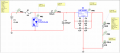
Crutschow is right!! I had one of those regulators oscillating at several megahertz and none of the voltages were even close to right. Use the recommended value, 0.1 Mfd, or possibly 0.33Mfd, right at the IC. The 10 Mfd caps can be farther away. And you will need a heat sink.
 

Thread Starter

andrei.mita

Joined Jun 19, 2018
25
The reason is given in the datasheet. The input capacitor is only required if the regulator is a "long" distance from the voltage source. The output capacitor is optional, and improves transient response.
Which capacitor has such a large ripple current, and why?
It is now obvious I don't get the datasheet right, or fully understand how capacitors work in my setup.
I was under the impression the caps smooth the input and output voltage, which I still think they do, but I also believed the ripple current is the current "traveling" through the circuit. That seems not to be correct and I have to do some more reading. The datasheet for ECA1HM100 shows 65mA which is a lot less than what I have. I think I'm far off from what it actually means.
 

Thread Starter

andrei.mita

Joined Jun 19, 2018
25
Hello,
The you are shorting the zener and will have no output voltage.
Bertus
I'm an idiot and I just woke up. Before using the zener diode, the housing was connected to the series resistor and the input pin of the Arduino. With the zener, the housing is connected to the series resistor, input pin and the zener diode. Don't know where my previous post came from.
 

Thread Starter

andrei.mita

Joined Jun 19, 2018
25
The voltage rating may be little more than "you can use this in a 6 V, 12 V or 24 V automotive system."

A minimum voltage may be necessary to help assure reliability if there really is a contact that moves over a resistive element.

If you don't have an oscilloscope and have meter that reads zero when set to AC and you try to measure a steady DC voltage (any handy battery not connected to some load will do to allow you check this, if you don't know), you can check for oscillation or high ripple voltage by simply measuring the voltage across each cap on the AC range. You would normally expect the AC voltage across the input cap to be some small fraction of a volt when actually in a car with the alternator running. The AC on the output cap should be no more than a few millivolts.
So it does mean I have to use at least 6V to power the sensor, right?

Nope, I don't have an oscilloscope and I will definitely do the AC experiment, thanks.
 

Thread Starter

andrei.mita

Joined Jun 19, 2018
25
I can't see more than 300mA at most in this circuit based on the zener being about 5V with current and a 10 Ohm sensor. 300mA at 13.6V - 8V = 0.3 * 5.8 = 1.68W. A typical TO220 has a Rja of around 65 degC/W so a 110degC temperature rise of the silicon inside the TO220 package. That'll hurt if you touch it!
I can't help thinking that the 6 to 24V spec though, applies to the switched output, not the sensor output and is actually a spec of the nominal system voltages anyway, ie 6, 12 or 24V systems otherwise the 24V spec does not make sense as a 24V system would be more like 28V with the engine running.
Automotive stuff usually has the chassis as the return path. A sensor may be different of course but either way, could I suggest that if you have the sensor in the ground leg fed through a 180 Ohm resistor (arbitrary but trying to keep power losses down and sensing voltage range up) from your 8V regulator then your arduino would see between 420 mV and 4 V over the full scale so a little headroom at the top and reasonable (?) resolution in the reading, 40 mA maximum current and less than 250 mW heat in the regulator. I am still not convinced that the sensor can handle 40 mA of current. Sensing elements generally don't like to be getting hot as heat typically throws readings off, just in general terms for these things if you catch my drift.

There is something else you should know about automotive power, a 12V system can and often does have spikes up to 60V and your circuit is relying on a modest little cap and a bit of impedance in wires to keep those spikes at bay. I'd suggest a series inductance on the positive input of at least 100uH but check the self resonant frequency to make sure the intra-winding capacitance doesn't just couple the spikes straight through as if no inductor were there. Follow that with an electrolytic 1000uF or better 2,200uF capacitor as well as smaller ceramic caps because the 780x regulators hate a high Z source. The electrolytics don't need to be special if you have a good ceramic cap between 100nF to 1uF (or both) in parallel with it and up close and personal with the regulator.
Indeed, 300mA is the max when the sensor is at the lowest stated values, 10ohm. My measurements indicated it will drop to 8.5 from time to time so I did all my calculations based on 8ohm. Sorry for the confusion.

I agree, in this case the switched output might be the reason for having a minimum of 6V as working voltage, but the other two sensors I have (NTC temp sensors) do not have the contact and indicate the same minimum voltage. Could it be just because or to indicate, as you said, the automotive industry nominal voltages?

The last two part are very very interesting, but I don't fully get them.
Where should I add the 180ohm resistor?

The last part is even more confusing but I'll get back to it after I understand the above one.
 

Janis59

Joined Aug 21, 2017
1,894
The caps get hot, thats a widespread symptom if their polarity is vice versa. If input wires are crossed then LDO will get hot too, thus this is first what must be checked.
If no, the next may be high frequency oscillations at tablet. Just look it by oscilloscope and apply a high freq paraleeling caps.
 

MisterBill2

Joined Jan 23, 2018
27,501
There are two issues here, the first one being that if the sensor body is grounded, as it would be in an automotive application, then you don't have the circuit as posted. Instead, one side of the sensor is grounded, so it must have a series resistor to limit the current. The other issue is that the regulator MUST HAVE the bypass capacitors very close to the pins. The applications notes say within 0.1 inch, less than 2mm. This is something that can not be ignored, because the regulator will definitely oscillate. AND, it may also be that the 10 Mfd capacitors are connected in reverse, or that they are damaged and have excessive leakage current..

One more thing is that a zener diode is not a good choice for voltage regulation in applications where good regulation is required. Use another power tab regulator, an LM7805, to power your arduino board, but be certain to install the required bypass capacitors very close to the device. I suggest finding an application note on the LM7805 and understanding what it tells about bypassing the power terminals. It will provide a valuable education.
 

Thread Starter

andrei.mita

Joined Jun 19, 2018
25
There are two issues here, the first one being that if the sensor body is grounded, as it would be in an automotive application, then you don't have the circuit as posted. Instead, one side of the sensor is grounded, so it must have a series resistor to limit the current. The other issue is that the regulator MUST HAVE the bypass capacitors very close to the pins. The applications notes say within 0.1 inch, less than 2mm. This is something that can not be ignored, because the regulator will definitely oscillate. AND, it may also be that the 10 Mfd capacitors are connected in reverse, or that they are damaged and have excessive leakage current..

One more thing is that a zener diode is not a good choice for voltage regulation in applications where good regulation is required. Use another power tab regulator, an LM7805, to power your arduino board, but be certain to install the required bypass capacitors very close to the device. I suggest finding an application note on the LM7805 and understanding what it tells about bypassing the power terminals. It will provide a valuable education.
The caps are right next to the voltage regulator, can't connect them any closer and this might be the actual reason why they get hot. I can't find anywhere in the datasheet that information, within 0.1in/2mm.

Maybe I don't get what you are saying, but the zener diode is not use regulate the voltage for powering up the arduino. It only limits the voltage that goes to the input pin should it exceed 4.7V so I don't ruin the board.
 

AlbertHall

Joined Jun 4, 2014
12,625
The caps are right next to the voltage regulator, can't connect them any closer and this might be the actual reason why they get hot. I can't find anywhere in the datasheet that information, within 0.1in/2mm.

Maybe I don't get what you are saying, but the zener diode is not use regulate the voltage for powering up the arduino. It only limits the voltage that goes to the input pin should it exceed 4.7V so I don't ruin the board.
Yes, I expect the caps get hot because they are near the regulator.
Yes, the zener is OK for that purpose.
 

MisterBill2

Joined Jan 23, 2018
27,501
Unfortunately the 10Mfd capacitors don't do much good at the megahertz frequencies that the regulators oscillate at. I had an almost 20 volt sine wave on a 12 volt supply bus because of not having the correct capacitors close enough. The reason is that electrolytic capacitors such as the 10Mfd ones have too much effective series inductance. At least that is the explanation that I got from the folks who wrote the application notes back in 1976. One more question is what is the voltage rating for those capacitors? Only two things make capacitors heat up, which are excessive leakage current, and excessive charge-discharge current, which can be caused by voltage regulator oscillation. Reversed connections will certainly cause the excessive leakage current, even more than a moderate overvoltage applied.
The zener diode protecting the input makes sense, I didn't realize that the module was powered from a different source.
 

Thread Starter

andrei.mita

Joined Jun 19, 2018
25
I got a lot more than I expected from this thread and I thank you all for the huge amount of information.
It is clear now that the design will not work properly.
First, some of you noted the case is grounded, and indeed this is a fact I forgot to take into account. This reason is enough for the voltage divider not to work. Second, the power dissipated is to much and if I take into account the board will run probably in an ambiental temp of 60-80C, the heat sink needed is probably around 4C/W and becomes huge. Plus all the components get very hot at this voltage/current.

As some of you suggested, I'll try the constant current approach as it solves the grounded case issue (I think) and I can limit the current at a reasonable 27mA. I've ordered some LM317 and correct caps for it and will have to run some new simulations and try it on the breadboard.

Will open a new thread with the outcome and probably new questions.

Thanks,
Andrei
 
The caps are right next to the voltage regulator, can't connect them any closer and this might be the actual reason why they get hot. I can't find anywhere in the datasheet that information, within 0.1in/2mm.

Maybe I don't get what you are saying, but the zener diode is not use regulate the voltage for powering up the arduino. It only limits the voltage that goes to the input pin should it exceed 4.7V so I don't ruin the board.
I think you might have been given some bad directions about the caps around the regulator. The distance limit in the 780x data sheets, and I think it was only the old National Semiconductor data sheet that even mentioned it was actually 0.5" but really, I wouldn't lose too much sleep over it. That series of regulator are an emitter follower configuration and not an LDO as has been claimed. They are inherently quite stable with almost any reasonable capacitance on the input and output. They are not prone to spontaneous eruptions of oscillations at any frequency. If you were using an LDO on the other hand, where the pass transistor is not in emitter / source follower configuration (LDO output is typically from collector or drain of the pass transistor) then the output caps are often critical. But as you are using the industry standard, everybody knows them, everybody loves them, everybody uses them and nobody has a problem with them, 780x regulators just put in a couple of caps as suggested and don't give it another thought unless it gets stinking hot (case temp over say 100degC at 25degC ambient) or the smoke leaks out. Smoke leaks are bad. ;)

The only problems I can see with the zener is that it is not guaranteed to clip the voltage to less than Vcc of the arduino (although it is also very unlikely to let the voltage get high enough to push the ESD protection diodes into forward conduction) and a 5W zener will probably be a bit leaky which may or may not interfere with the readings (although circuit impedances are pretty dang low so maybe not a big deal either). Other than that I think you did well in recognising the potential problem and coming up with an elegant and simple solution being a single component.
 
It is now obvious I don't get the datasheet right, or fully understand how capacitors work in my setup.
I was under the impression the caps smooth the input and output voltage, which I still think they do, but I also believed the ripple current is the current "traveling" through the circuit. That seems not to be correct and I have to do some more reading. The datasheet for ECA1HM100 shows 65mA which is a lot less than what I have. I think I'm far off from what it actually means.
Your understanding doesn't seem quite as bad as you fear. you are correct that the circuit current and the cap ripple current are not directly linked. If you were to apply an AC voltage to a cap then the cap would be charging and discharging and that means a current moving into and out of the cap and that is the ripple current. If the voltage on a cap is steady, no current flows into or out of the cap and the ripple current is therefore zero.

In your circuit the caps are there to provide a low impedance voltage source on the input and a low impedance shunt for the output of the regulator and a low impedance source for the load if a step increase in load current is too fast for the regulator to respond to the cap takes up the slack until the regulator can catch up.

The 65mA ripple current spec should be fine. Just put a 100nF plastic or ceramic cap in parallel and closest to the regulator.
 

MisterBill2

Joined Jan 23, 2018
27,501
I think you might have been given some bad directions about the caps around the regulator. The distance limit in the 780x data sheets, and I think it was only the old National Semiconductor data sheet that even mentioned it was actually 0.5" but really, I wouldn't lose too much sleep over it. That series of regulator are an emitter follower configuration and not an LDO as has been claimed. They are inherently quite stable with almost any reasonable capacitance on the input and output. They are not prone to spontaneous eruptions of oscillations at any frequency. If you were using an LDO on the other hand, where the pass transistor is not in emitter / source follower configuration (LDO output is typically from collector or drain of the pass transistor) then the output caps are often critical. But as you are using the industry standard, everybody knows them, everybody loves them, everybody uses them and nobody has a problem with them, 780x regulators just put in a couple of caps as suggested and don't give it another thought unless it gets stinking hot (case temp over say 100degC at 25degC ambient) or the smoke leaks out. Smoke leaks are bad. ;)

The only problems I can see with the zener is that it is not guaranteed to clip the voltage to less than Vcc of the arduino (although it is also very unlikely to let the voltage get high enough to push the ESD protection diodes into forward conduction) and a 5W zener will probably be a bit leaky which may or may not interfere with the readings (although circuit impedances are pretty dang low so maybe not a big deal either). Other than that I think you did well in recognising the potential problem and coming up with an elegant and simple solution being a single component.
The oscillation was certainly real, whatever the cause. And yes, it was a National part, at the time they were the sole source of 7805 devices, I think.. But in laying out PC artwork it was never any great effort to put the caps very close and have a very low inductance connection. Of course, while my layouts were not as tight as possible, neither did they spread all over. Hand assembly is more tolerant than machine stuffing it seems. The tight regulation and fast response time of more recent regulators does require correct bypassing to avoid oscillation, thus it still makes sense to keep the 0.1Mfd caps close.
 
Indeed, 300mA is the max when the sensor is at the lowest stated values, 10ohm. My measurements indicated it will drop to 8.5 from time to time so I did all my calculations based on 8ohm. Sorry for the confusion.

I agree, in this case the switched output might be the reason for having a minimum of 6V as working voltage, but the other two sensors I have (NTC temp sensors) do not have the contact and indicate the same minimum voltage. Could it be just because or to indicate, as you said, the automotive industry nominal voltages?

The last two part are very very interesting, but I don't fully get them.
Where should I add the 180ohm resistor?
The last part is even more confusing but I'll get back to it after I understand the above one.
I should apologise for not posting a schematic in the first place. My usual CAD package (altium) has decided to be difficult and now fails to launch so I've used a drawing package to come up with the following very very sad excuse for a circuit diagram. The only thing not shown is the zener diode and that's only because I ran out of patience with the drawing tool. The uC should get from this circuit between 420mV and 4V over the full scale.
If you were to use the internal reference in the uC which is a lower voltage then the 180R resistor would be a bigger value and the current in the sensor would also be lower which can't be a bad thing.

I'll attach another circuit for the last part of my previous post. Basically, in a 12V automotive environment there are regular voltage spikes up to around 60V happening all the time when the engine is running. My suggestion is to put a series inductance in the power input to act as an appreciable impedance to the spikes then to use a cap to absorb what energy of the spike happens to get through the inductor. The other way to think of it is as a second order low pass filter. In either case the time domain or frequency domain characteristics of the spikes may not be well defined generally but I did find this in a search:
http://www.fordemc.com/docs/requirements.htm
If you look through that document, the load dump events should be a very rare thing to the point you could count them as 'an acceptable risk' for a hobbyist project. I had a contract a few years ago to design an intrinsically safe power supply for a 24V automotive environment (a gasoline tanker truck) and the input voltage spec maximum was 100V (from memory) so a load dump event became a normal condition of the input voltage to the power supply I designed. This is a fairly extreme condition for a hobbyist type project but not so much for a commercial product (that could never be repaired because the whole thing is encapsulated) that a customer would not want to be replacing every few years.
I don't know how you might want to handle that, design for it or not. That is your call obviously. I can help if you want and if you think you should design for it. It is I think, the most difficult anomaly in automotive power systems to deal with because it is not just a very short spike that can be filtered out with an inductor and capacitor but hangs around for half a second or so, which is why it was incorporated into my spec as a normal condition of the input voltage.

I hope that clarifies my previous post but let me know if I have failed to communicate ;)
Hope your experiments are going ok in the meantime.
 

Attachments

Thread Starter

andrei.mita

Joined Jun 19, 2018
25
I should apologise for not posting a schematic in the first place. My usual CAD package (altium) has decided to be difficult and now fails to launch so I've used a drawing package to come up with the following very very sad excuse for a circuit diagram. The only thing not shown is the zener diode and that's only because I ran out of patience with the drawing tool. The uC should get from this circuit between 420mV and 4V over the full scale.
If you were to use the internal reference in the uC which is a lower voltage then the 180R resistor would be a bigger value and the current in the sensor would also be lower which can't be a bad thing.

I'll attach another circuit for the last part of my previous post. Basically, in a 12V automotive environment there are regular voltage spikes up to around 60V happening all the time when the engine is running. My suggestion is to put a series inductance in the power input to act as an appreciable impedance to the spikes then to use a cap to absorb what energy of the spike happens to get through the inductor. The other way to think of it is as a second order low pass filter. In either case the time domain or frequency domain characteristics of the spikes may not be well defined generally but I did find this in a search:
http://www.fordemc.com/docs/requirements.htm
If you look through that document, the load dump events should be a very rare thing to the point you could count them as 'an acceptable risk' for a hobbyist project. I had a contract a few years ago to design an intrinsically safe power supply for a 24V automotive environment (a gasoline tanker truck) and the input voltage spec maximum was 100V (from memory) so a load dump event became a normal condition of the input voltage to the power supply I designed. This is a fairly extreme condition for a hobbyist type project but not so much for a commercial product (that could never be repaired because the whole thing is encapsulated) that a customer would not want to be replacing every few years.
I don't know how you might want to handle that, design for it or not. That is your call obviously. I can help if you want and if you think you should design for it. It is I think, the most difficult anomaly in automotive power systems to deal with because it is not just a very short spike that can be filtered out with an inductor and capacitor but hangs around for half a second or so, which is why it was incorporated into my spec as a normal condition of the input voltage.

I hope that clarifies my previous post but let me know if I have failed to communicate ;)
Hope your experiments are going ok in the meantime.
And I thought it was so so simple to read the sensor and just pass the value from the Arduino to my phone via Bluetooth :)
I mean, what could go wrong with a voltage divider?

Thanks a lot for taking the time pass this information. I never thought of the spikes because 1. I though the voltage will never go above 13.8V, 2. the car I'm working on has very little electronics, the most advanced thing in there is a voltage sensing relay.

Being an engineer myself and with the new questions/knowledge I now have, I can't help but do things properly.

So I think it's safe to split the project in 2: first, need to follow your directions and filter out the spikes, then decide if I should go with the voltage or current source.

Looking at the schematic for the filter, I assumed the inductance is 100uH and the capacitor is 2200uF (from a previous post from you).
The fuse (just by guessing) I'll say it's 1A.
Now, the TVS. This is the first time I hear about it and after some searches I assume is Transient Voltage Suppressors Diode.
I could not find one on http://www.falstad.com/circuit/ nor in Multisim, but maybe I'm looking for the wrong stuff. I tried with something that resembled a TVS but the powers and amps where way up.

I'm really trying to understand now how the safe power supply works.
 

Attachments

The oscillation was certainly real, whatever the cause. And yes, it was a National part, at the time they were the sole source of 7805 devices, I think.. But in laying out PC artwork it was never any great effort to put the caps very close and have a very low inductance connection. Of course, while my layouts were not as tight as possible, neither did they spread all over. Hand assembly is more tolerant than machine stuffing it seems. The tight regulation and fast response time of more recent regulators does require correct bypassing to avoid oscillation, thus it still makes sense to keep the 0.1Mfd caps close.
Actually the schematic is all wrong.
One curiosity. How do you calculate the capacity and inductance to get a proper LC filter?
Your schematic looked pretty damn good to me, and very right! Except for the TVS diode showing a forward biased diode that will pop the fuse instantly. My apologies for my incomplete posts. You guess right about the L and C values I suggested. The values I have quoted are just what I would start with. To make a properly designed filter the noise to be filtered needs to be enumerated and the maximum noise that can be tolerated needs to be known as well. Then the values can be defined properly. If you use the values I suggested you should have at least a good chance of no major problems with electrical noise and the 100uH inductor is likely to remain inductive over the frequency band of interest. A higher value will have a lower self resonant frequency and therefore will become capacitive at a lower frequency as well.
The fuse will need to be a slow blow or time lag type because of the inrush current into the caps. For example:
https://www.digikey.com.au/product-detail/en/bel-fuse-inc/0659C2000-12/507-2005-ND/5843989
The caps around the 7808 should be an electro and a ceramic in parallel on the input and output. I'd suggest 100nF and 100uF.
For the TVS, have a look at
https://www.digikey.com.au/product-detail/en/littelfuse-inc/SMBJ15A/SMBJ15ALFCT-ND/285981
or if you want something with more current capacity
https://www.digikey.com.au/product-detail/en/littelfuse-inc/5.0SMDJ15A/5.0SMDJ15ACT-ND/1835377
My apologies again for the lack of detail in my posts. Luckily you are also an engineer and clever enough to correctly fill in the blanks I leave:). If my CAD (Altium) had not died I would be using schematics more and the details would be there.
 
Top