Are you just looking for someone to take your poll?
I'm gonna go out on a limb and guess that "Any" is going to win.
It will help others help you if you take the time to edit your pictures so that they aren't 10x as big as they need to be and so that they are oriented correctly.
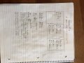
As for where to start, here's a hint. Read the problem and do the first thing they told you to do: "Redraw the circuit and use the following values."
Then look at that redrawn circuit and see which measurements don't make sense for the circuit as drawn.
Are you just looking for someone to take your poll?
I'm gonna go out on a limb and guess that "Any" is going to win.
It will help others help you if you take the time to edit your pictures so that they aren't 10x as big as they need to be and so that they are oriented correctly.
I'm getting an error when I try to open the attachment in the body of the post (but I can see the image file that was attached -- is it the same thing?).
What is "circuit 2" -- and how does it relate to Problem #3.
Which resistor is shorted? How do you know? Area all of the readings consistent with that resistor being shorted?
In case you have not figure it out yet, yes you add R1+R2 and separately R3+R4, then compute the two results as being in parallel. You can then calculate the current and compare it to the specified value. You may also have to use current division to figure this out.
This most recent upload of yours however does not show your determination of what is not right.
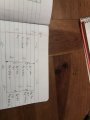
Here is an improved version of your upload. Nice hardwood floor BTW
In case you have not figure it out yet, yes you add R1+R2 and separately R3+R4, then compute the two results as being in parallel. You can then calculate the current and compare it to the specified value. You may also have to use current division to figure this out.
This most recent upload of yours however does not show your determination of what is not right.
Here is an improved version of your upload. Nice hardwood floor BTW View attachment 121292
Why do you keep forcing people to open files that are several times larger than they need to be and require people to read sideways. In less than one minute (literally) using Paint or (other the equivalent on whatever OS you are using) you could have posted this instead:
What is the total current you are expecting?
What is the total current that is being measured?
Are these acceptably close? If not, then you have a problem.
The next step is to ask yourself what single component failure could turn the circuit from what you expect into one that matches the measurements.
Ask yourself what you would expect the voltages and total current to be in the eight most likely failure modes, namely one of the resistors failing as either an open or a short.
You can narrow this down before you even start. Consider the two basic failure modes -- open and short.
If one of the resistors fails as a short, do you expect the total current to be greater or less than what you expect?
If one of the resistors fails as an open, do you expect the total current to be greater or less than what you expect?
Which of these is consistent with the discrepancy between what you expect and what the total current is?
I'm getting an error when I try to open the attachment in the body of the post (but I can see the image file that was attached -- is it the same thing?).
What is "circuit 2" -- and how does it relate to Problem #3.
Which resistor is shorted? How do you know? Area all of the readings consistent with that resistor being shorted?
Why do you keep forcing people to open files that are several times larger than they need to be and require people to read sideways. In less than one minute (literally) using Paint or (other the equivalent on whatever OS you are using) you could have posted this instead:
Are these acceptably close? If not, then you have a problem.
The next step is to ask yourself what single component failure could turn the circuit from what you expect into one that matches the measurements.
Ask yourself what you would expect the voltages and total current to be in the eight most likely failure modes, namely one of the resistors failing as either an open or a short.
You can narrow this down before you even start. Consider the two basic failure modes -- open and short.
If one of the resistors fails as a short, do you expect the total current to be greater or less than what you expect?
If one of the resistors fails as an open, do you expect the total current to be greater or less than what you expect?
Which of these is consistent with the discrepancy between what you expect and what the total current is?
Thank you ! the step by step process to begin to figure this out is great info ..I'm kinda lost as you can see , I will send my future files in a better format before I post next time ..thx
I'm not sure ? I'm thinking the technicians readings are incorrect and voltage across circuit 1 have been misread? according to all of my calculations? but any input would be helpful .thx
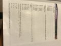
r1 voltage drop (270)(0.0154)=4.158
r2 voltage drop (570)(0.0154)=7.854
=12.012
r3 voltage drop(470)(0.015)=7.238
r4 voltage drop(330)(0.0154)=5.082
=12.32
the sum of the applied voltage drop in a series circuit must equal the applied voltage .
so still not sure on why e2 is o v ?
I'm not sure ? I'm thinking the technicians readings are incorrect and voltage across circuit 1 have been misread? according to all of my calculations? but any input would be helpful .thx
Think about what you are saying. The problem makes it very clear that there is something wrong with the circuit -- the entire point of the problem is for you to figure out what the most likely problem is. You are given the results of measurements made on the actual circuit to use in making that determination. The fact that there is something wrong means that the measurements will not be what you would expect based on the circuit schematic. Does it really make sense to conclude that the measurements weren't done correctly?
This is like being told that the tires on a car are wearing abnormally and, when told that the tire pressure measurement is 20 psi, concluding that the person taking the reading must have misread the pressure gauge since the tire sidewalls clearly state that the tires are supposed to be inflated to 35 psi.
r1 voltage drop (270)(0.0154)=4.158
r2 voltage drop (570)(0.0154)=7.854
=12.012
r3 voltage drop(470)(0.015)=7.238
r4 voltage drop(330)(0.0154)=5.082
=12.32
the sum of the applied voltage drop in a series circuit must equal the applied voltage .
so still not sure on why e2 is o v ?
 Facebook
 Google
 GitHub
 Linkedin
 295.2 KB Views: 21
 347.3 KB Views: 20

")