Voltage Divider

Thread Starter

beeson76

Joined Apr 19, 2010
211
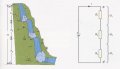
Im reading up on Voltage Divider Circuits on the internet and this problem was presented. I figured out the values for the First Figure...but the Second Figure is giving me problems. Can anyone tell me how I would go about figuring out the values for the second figure. For the value for R2 and R3, would I figure it out by using it as a Parallel Circuit. And would the voltage coming "out" of the Voltage Divider be the same voltage as in the First Figure (9v)? I will stop there as far as questions:)

Thanks for your help.
 

Attachments

BSomer

Joined Dec 28, 2011
434
Yes you would use the parallel math because when you close the switch R2 is now in parallel with R3. Since you added a resistor to your network it changes the total resistance, so your output voltage and total current will also change. You need to figure out what the parallel resistance will be then do the math to figure out the Vout.
 

Jony130

Joined Feb 17, 2009
5,487
I would go about figuring out the values for the second figure. For the value for R2 and R3, would I figure it out by using it as a Parallel Circuit.
Yes, R2 and R3 are now connect in parallel. So yo need to find the equivalent resistance.

And would the voltage coming "out" of the Voltage Divider be the same voltage as in the First Figure (9v)
No, the voltage also change.
 

Thread Starter

beeson76

Joined Apr 19, 2010
211
I have as a parallel resistance for R2 and R3 to be 3125 ohms. So R1 still has a resistance of 6000 ohms right. Is this correct so far?

I really don't know how to figure current though. Do I figure it for the whole circuit or would I divide it into "separate parts" such as R1 by itself and R2 and R3 in another part (them being in a parallel circuit) (same thing with R1 and R2 being in a Voltage Divider Circuit.)
 

Thread Starter

beeson76

Joined Apr 19, 2010
211
http://www.wisc-online.com/objects/ViewObject.aspx?ID=SSE5103

Page 6.

Here is where I am getting this information. In figure 2 I have the voltage out as being 11.826v. For my voltage divider resistances I am using 6k ohm for R1 and 3125k ohm for R2. This would be 9125v. 6000/9125 x 18 = 11.826v. But on the website they are saying that I should have 6 volts coming out of the voltage divider...the voltage drop over R3.

And then I have no idea where they are getting the current readings from:) For example 2mA over R1 when the switch is "on".
 

Jony130

Joined Feb 17, 2009
5,487
In page 6 I see this diagram


So we have three resistor and they all have 6KΩ resistance.

When the switch is open, the output voltage (across the bottom 6K resistor R2) is equal to:

V2 = I * R2

I = Vbat/(R1 + R2)


V2 = I * R2 = Vbat/(R1 + R2) * R2 = Vbat * R2/(R1 +R2) = 9V

And now if we close the switch we connect R3 parallel to R2.
So equivalent resistance will be equal to

Reg = R2 * R3/ (R1 + R2) = 36/12 = 3KΩ

And the output voltage will drop to

V2 = Vbat * Req/( R1 + Req) = 18V * 3/9 = 6V
 

Attachments

Thread Starter

beeson76

Joined Apr 19, 2010
211
Thanks Jony130.

I appreciate the explanation. It will take some time to grasp this but I know that after reading and rereading it along with some paper and pen, I will get the hang of it:)

Thanks again for the reply.
 

BreadCrum6

Joined Aug 17, 2011
18
The current in the PDF says .0015 mA when it should be .0015 A. Maybe that may have been the problem.

Also in the second figure when R3 is added both Vout and I1 also change.
 

Thread Starter

beeson76

Joined Apr 19, 2010
211
So equivalent resistance will be equal to

Reg = R2 * R3/ (R1 + R2) = 36/12 = 3KΩ

And the output voltage will drop to

V2 = Vbat * Req/( R1 + Req) = 18V * 3/9 = 6V

Ok. It makes sense now. Only questions are very simple ones...what is Reg and Req in the formulas. And where do you get those forumlas from:) For example for parallel resistances, Im familiar with 1 / (1/Resistance1) + (1/Resistance2). Just so I know.

Thanks
 

BillB3857

Joined Feb 28, 2009
2,570
I'm curious as to what formula you used to find the parallel resistance of R2 and R3 to be 3125 ohms. (Post #4) Just trying to keep you from getting off on a questionable path.
 

BreadCrum6

Joined Aug 17, 2011
18
Ok. It makes sense now. Only questions are very simple ones...what is Reg and Req in the formulas. And where do you get those forumlas from:) For example for parallel resistances, Im familiar with 1 / (1/Resistance1) + (1/Resistance2). Just so I know.

Thanks
I think he made some typos. I'm assuming Reg = Req which is the equiv. resistance for the parallel resistors.

Ra*Rb/(Ra+Rb)
 

Jony130

Joined Feb 17, 2009
5,487
Ok. It makes sense now. Only questions are very simple ones...what is Reg and Req in the formulas. And where do you get those forumlas from:) For example for parallel resistances, Im familiar with 1 / (1/Resistance1) + (1/Resistance2). Just so I know.

Thanks
To find equivalent resistance for the parallel resistors we use this formula:
1/Requiv = 1/R1 + 1/R2 ... + 1/Rn

But when we have only two resistor connect in parallel the equation will be look like this:

1/Requiv = 1/R1 + 1/R2 = R2/(R1 * R2) + R1/(R1 * R2) = (R2 + R1 )/ (R1 * R2)

So Requiv = (R1 * R2)/(R1+R2)
 

Thread Starter

beeson76

Joined Apr 19, 2010
211
Ok. I understand now the Req (Resistor Equivalent). I was using the formula for more than 2 resistors in parallel. I needed to use the formula for 2 parallel resistors. So I got the resistors down to 3000 ohms each. I and figured out the out the V2 voltage. I was not substacting the voltage drop across R1 which was 12 from the total voltage which is 18. But this raises another question. What is the voltage drop across R2? If voltage drop across R1 is 12 and the V2 is 6. How would I figure the voltage drop across R2?

Thanks again for all the help. I know these may be simple questions, but for someone trying to learn from just reading and experimenting, some things don't quite make sense.
 

Jony130

Joined Feb 17, 2009
5,487
But V2 is the voltage between V2 and gnd.
So voltage across R2 is equal to V2
Remember that if elements are connect in parallel they will have the same voltage across them.
 

Thread Starter

beeson76

Joined Apr 19, 2010
211
Thanks Jony130. So your saying that the Voltage Drop across R2 and R3 are both 6 volts because they are in parallel? Is that correct. I was trying to do ohms law to try to figure it out and it just wasnt working for me:):)

Also with parallel circuits, the current can be different for different components. I am only use to figuring ohms law for serial circuits. (for example a voltage source of 18 volts for 3 resistors with 110, 220, 330 has a current of 27mA.--each having a voltage drop of 3, 6, and 9 volts) Put that with the 3 resistors in parallel, and I would have to do some figuring and reading:)
 

Jony130

Joined Feb 17, 2009
5,487
Thanks Jony130. So your saying that the Voltage Drop across R2 and R3 are both 6 volts because they are in parallel? Is that correct.
Yes the voltage is the same.
In series circuit we have the same current but the voltage is divided in each individual elements.


for example a voltage source of 18 volts for 3 resistors with 110, 220, 330 has a current of 27mA.--each having a voltage drop of 3, 6, and 9 volts) Put that with the 3 resistors in parallel, and I would have to do some figuring and reading
Simply use Ohms law to find the current in each individual component.

In parallel circuit the voltage is the same but the current is splitting between the branches.
So we have a current divider


Attachments

Last edited:

Jony130

Joined Feb 17, 2009
5,487
Look at those two diagrams

The first diagram shows I Kirchhoff's law.

2.PNG


Current entering the node must be equal the current that is leaving the node.

And this diagram show II Kirchhoff Law

1.PNG
 
Last edited:

sausages

Joined Mar 8, 2007
23
Hi,
Sorry to hijack the thread but I've got a voltage divider question too and I thought I might as well put it here. It's been three years since I've done any kind of electronics work so I'm a little rusty

I was reading through the worksheet :
Rich (BB code):
http://www.allaboutcircuits.com/worksheets/e_divide.html
Select All
and I've run into problems with two of the questions I looked at.

Question 16
I understand that the wiper @25% sets the equivalent resistance of the pot to 1K25Ω . I then used the voltage divider formula and got Vout to equal 4.44V.
However the answer given is 1.29V.

Question 18
I'm having trouble calculating the equivalent resistance in this question. I've been scratching my head but I'm finding it hard to get my head around it. Are the two 5K resistors supposed to be added together in series and then, is the 100K in parallel with that?

I'm confused and I would greatly appreciate any help.

Thanks,
Damien
 
Top