 Facebook
 Google
 GitHub
 Linkedin
Dear Friends,
I have a doubt. It may seem to be very simple for you.
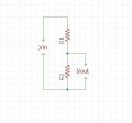
What is the problem in using a voltage divider in Ohmic range other than in Kilo Ohm range?.
Or can I choose a resistor combination in parallel as resistor R1 and R2 in the voltage divider?.
I have a doubt. It may seem to be very simple for you.
What is the problem in using a voltage divider in Ohmic range other than in Kilo Ohm range?.
Or can I choose a resistor combination in parallel as resistor R1 and R2 in the voltage divider?.
Attachments
-
 49.9 KB Views: 34


