voltage divider from buck boost and resistors, weird goings on

Thread Starter

ninjaman

Joined May 18, 2013
341
hello

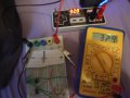
I want to make a 15v dual power supply from a buck boost converter I bought on ebay
step up
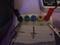
I connect a 9v battery to it and get 32.8v max. I have two resistors making a divider. the resistors are 383kohm.
I measure 32.8v across the supply, I have these outputs (+-) going to breadboard connected to the resistors. the supply at the breadboard is 32.7v and across individual resistors 13.7v
so it is loosing some volts somewhere. I went up to 32.8 from 30 as I wasn't getting the output across the resistors that I wanted. I still cant get it at 32.8v

any suggestions on this?

thanks

simon
 

b1u3sf4n09

Joined May 23, 2014
113
Did you measure the resistors? Did you measure the conductor resistance of the board? If you measure the proper output at the breadboard, then it would logically follow that the issue must be in your board or your load. A picture of your setup may also help.
 

Thread Starter

ninjaman

Joined May 18, 2013
341
hello
this is the set up
I tried a new battery as the one in there was 7 volts. still the same result.
what could I do to test the converter, is there some method of determining whether a component has failed?

thanks

simon
 

Attachments

BobTPH

Joined Jun 5, 2013
8,954
What you are trying to make is called a virtual ground. You can do this with resistors, but only if you are going to have very little current going to this ground. A rule of thumb would be 1/10 of the current going through the divider.

If you want to continue the virtual ground approach you would need a buffer amplifier for the ground. An opamp would work up to about 20mA. If higher, you would need the opamp plus a push pull stage of power transistors.

And even then, if quick response is needed it would not be that good.

Better solution:

Get two of the boost converters, connect each one to a separate 9V battery, then connect the + of one output to the - of the other and use that as your ground.

Bob
 

b1u3sf4n09

Joined May 23, 2014
113
Measure your resistors.

It looks like you are using resistors with 5% tolerance. Even a small difference in resistance between the two will present a different voltage across each. They are drawing about 42.8 uA, which means that a resistor at +5% will have a voltage drop of 17.2V, and a resistor at -5% will have a drop of 15.3V (this was quick math done on scratch paper, so rounding was involved). The reduction in voltage can be attributed to either out-of-tolerance resistors or to an extremely inefficient power supply. You should see a larger voltage drop across the unmeasured resistor (~19V).
 

Thread Starter

ninjaman

Joined May 18, 2013
341
hello

please could you explain the math to me b1u3sf4n09, the voltage across both is the same. I just took a picture of one, the resistors measure the same 385kohm. they are 5% tolerance.

thanks

simon
 

BobTPH

Joined Jun 5, 2013
8,954
Did you read my post? Your circuit will not work, no matter what resistors you use. I gave you 3 options that might work, depending on the currents you need to draw from the dual supplies.

Also, the sum of the voltages across the two resistors has to be equal to the output of your boost converter. From the measurements you gave us, they are not. So your measurements are wrong.

Bob
 

b1u3sf4n09

Joined May 23, 2014
113
please could you explain the math to me b1u3sf4n09, the voltage across both is the same. I just took a picture of one, the resistors measure the same 385kohm. they are 5% tolerance.
simon
5% of 383kohm is 19.15kohm, so +5% would equate to 402.15kohm, and -5% would equate to 363.85kohm. Multiplying these values by the current draw will give you your highest and lowest voltage drop assuming the resistors are within tolerance: 15.7V to 17.2V.
 

JWHassler

Joined Sep 25, 2013
306
hello
this is the set up
I tried a new battery as the one in there was 7 volts. still the same result.
what could I do to test the converter, is there some method of determining whether a component has failed?

thanks

simon
You have two, 385K resistors in series across 38 volts.
One of the two resistors is further parallelled by the resistance of your voltmeter.
If Rmeter is assumed to be 1 MegOhm (a fair? assumption for an inexpensive DVM), the voltage reading would be about 13-ish volts.
upload_2014-11-5_9-5-32.png
 

b1u3sf4n09

Joined May 23, 2014
113
That's a good point, JWHassler. With such a small current, the multimeter is probably loading the circuit.

ninjaman - Try reducing your resistors by a few decades. Some 5k or 10k resistors should remove the loading effect.
 

BobTPH

Joined Jun 5, 2013
8,954
That's a good point, JWHassler. With such a small current, the multimeter is probably loading the circuit.

ninjaman - Try reducing your resistors by a few decades. Some 5k or 10k resistors should remove the loading effect.
Which will work with the multimeter, but will not work when he adds the load to the dual supply he is trying to create by using a voltage divider. This will not work, unless the current needed by the load is at least 10 times lower than the current through the voltage divider.
Bob
 

MMW

Joined Nov 6, 2014
1
JWHassler, BobTPH and b1u3sf4n09 are pointing you in the right direction:
You got a measuring error due to high impedances, and you need a buffered low-impedance center-point.

Consider using a single device called 'Virtual Ground Rail Splitter' the TLE2426 from TI, that also includes the resistors and sinks/sources 20mA.
It will definitely do better than any resistive divider you come up with.
 

BobTPH

Joined Jun 5, 2013
8,954
To find a real solution, we have to know how much current the dual supply needs to provide. I gave 3 possible solutions, based on different levels of current in an earlier post.

MMW gave another, which is really the same as my opamp solution.

Bob
 
Top