Voltage divider calculations.

Thread Starter

dansteely

Joined Feb 26, 2017
37
Hi All,

I have a working circuit with a split rail supply +35V 0V -35V

Elsewhere in the device I need +&- 15V at 20mA.

Ive used online calculators for the resistor values but If I use low value resistors they get hot and If I use high values the current available is too low.

All of the resistors I have in stock are 1/4 watt.

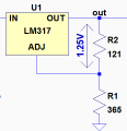
Would a pair of regulator IC's be the solution?

All advise would be most welcome.

Thanks
 

crutschow

Joined Mar 14, 2008
38,504
You could use an LM317 and an LM337.
The resistors for 15V output would be 121Ω from the output to the ADJ pin and 1.33kΩ from the ADJ pin to ground.
 

Thread Starter

dansteely

Joined Feb 26, 2017
37
Hi Crutchow, Thanks for the advice re the adjustable regulators.
I've been looking on CPC for fixed voltage type regs to simplify the circuitry and have found:
TS7815CZ (+15V) and L7915CV (-15V)

The only issue with these is the max input voltage (+35V) my measured rails (under load) is 34.5V.

Is that too close for comfort?
 

#12

Joined Nov 30, 2010
18,224
You could also use a pair of 15V 1W zeners.
Give them 20 ma to 25 ma from the 35V supply with (4) 1/4 watt resistors.

The bottom line is that about a half watt is involved in providing a 20 volt change at 20 ma by any analog method. That requires a watts worth of resistors or a 1/2 watt of scary hot resistors. Sorry. The laws of thermodynamics are messing with you.
 

WBahn

Joined Mar 31, 2012
32,829
Yes,
Hi Crutchow, Thanks for the advice re the adjustable regulators.
I've been looking on CPC for fixed voltage type regs to simplify the circuitry and have found:
TS7815CZ (+15V) and L7915CV (-15V)

The only issue with these is the max input voltage (+35V) my measured rails (under load) is 34.5V.

Is that too close for comfort?
Yes. That is the absolute maximum rating and you do not want to push that very hard. Now, if this is a hobby type application then you can probably get away with it for a long time. You will have to decide your risk tolerance for what you are doing.

What are your rails when not under load? If they are anything above 35 V, then you are violating the spec sheet and there is no guarantee what will happen.

Having said that, there is always margin built into spec sheets -- but you rely on that at your own peril. We've all done it -- hell, we've all patted ourselves on the back for it -- but it is important to know that when you dance with the devil, sooner or later the bill comes due.

There are some games you can play. One is to put a zener in series with the input to drop some of the voltage. Another is to put a resistive voltage divider that drops just enough to keep you comfortably within spec (which may or may not be possible).

You say you need 20 mA. Let's call it 30 mA to give a margin. The regular needs 23 V minimum input, so let's make it 25 V. That means we want to drop 10 V at 30 mA. That would be 300 mW. Let's cut that in half to 5 V at 30 mA giving us 150 mW for your 1/4 W resistor. So the resistor value would be 167 Ω. Let's make it 150 Ω. Now, under your 20 mA load, you will be dropping 3 V and have a 32 V input to the regulator. That gives you some margin. But when you aren't drawing any current the input voltage will still be 35 V, but this is probably okay because as soon as it started to draw current the voltage would drop. Still, let's say we want to drop in the vicinity of at least 1 V all the time. We would need a current of about 7 mA. Let's call it 5 mA. We could achieve this by placing a load resistor before the regulator input that is about 6.8 kΩ. It would be dissipating about 180 mW.

I'm not saying that the resistive approach is the best one -- merely trying to walk you through one way of coming up with a solution.

If you are dropping 20 mA through 10 V, then (unless you use a switch-mode converter) you need to get rid of 200 mW of heat one way or another. So why not put half, or so, of it in a passive series dropping element (resistor or zener) and the other half in the regulator?
 

eetech00

Joined Jun 8, 2013
4,705
Hi

Could use a 20v, 2W, zener and suitable resistor to drop the voltage to +/-20v.
Then use the LM7x15 to regulate from +/-20v to +/-15v.
 

Thread Starter

dansteely

Joined Feb 26, 2017
37
Hi All,

Thanks for all the helpful suggestions.

I'm going to go with the adjustable regulator solution as it gives me a safety margin on the input.

Cheers.

DS
 

WBahn

Joined Mar 31, 2012
32,829
Hi All,

Thanks for all the helpful suggestions.

I'm going to go with the adjustable regulator solution as it gives me a safety margin on the input.

Cheers.

DS
Be sure to do the power dissipation calculations and, if needed, heatsink the regulator accordingly.
 

WBahn

Joined Mar 31, 2012
32,829
You'd be better served by reading the data sheet. It not only tells you how to calculate the resistor values, but also other information about min/max values, proper bypassing, operational limits, calculating heat sink requirements.
 

crutschow

Joined Mar 14, 2008
38,504
Can you please explain the calculations behind the resistor values for the adjustable regs?
The formula uses a ratio to calculate the value but I use a piecemeal approach.
Those regulators regulate by maintaining a constant reference voltage from OUT to the ADJ pin (nominally 1.25V).
upload_2017-3-21_13-26-26.png
Since the spec states that the minimum output current to maintain regulation is 10mA worst-case (below), the value for the resistance between the output and ADJ (R2) is selected to be 121Ω, which thus generates a constant output load current of 1.25V/121Ω = 10.3mA.
upload_2017-3-21_9-46-24.png
Since the ADJ pin is 1.25V below the output voltage, you then want to add a resistor (R1) to ground that generates (15V-1.25V)=13.75V for 15V out, with the 10.33mA current through R2 (the ADJ current of 100μA max. is small enough to be ignored in this calculation).
This give a value for R1 of (13.75V/10.33mA) = 1.33kΩ.

(As an exercise based upon your understanding of the above calculations, what output voltage does the shown value for R1 of 365Ω provide?)
 

Attachments

Last edited:

Thread Starter

dansteely

Joined Feb 26, 2017
37
Many thanks for the explanation. I'm away from home at the moment and will need a few hours concentration in a dark silent room to give you an answer...

I will come back to you on this....

Sincere thanks for your time and help with this.
 

WBahn

Joined Mar 31, 2012
32,829
As I am interested in this but don't want to spoil it for others, is there anyway to message you with my answer?
Since this isn't a homework problem, you don't have to be too concerned with unfairly giving away the answer, so
spoiler tags are a good way to go.
 

Ed Bray

Joined Feb 1, 2017
46
Since this isn't a homework problem, you don't have to be too concerned with unfairly giving away the answer, so
spoiler tags are a good way to go.
Cool, I'll have a go, first time for everything.

so 10.33ma x 0.365 = 3.77V so with the 1.25V across R2 would give an output of 5.02V give or take?
 
Top