I think you need to go back to first principles and review the proper opamp configurations and how to analyze them. For example if you replace all three resistors and connect an appropriate power supply you will have a voltage follower and by definition pin 2 and pin 4 will both have the same voltage and the difference between pin 1 and pin 2 will be very close to zero.
- It needs more attention. Pins 3 & 5 are the power connections, and the difference must be at least as large as the range of the input signal.
- Opamps start by computing the difference between the (+) or non-inverting input, and the (-) or inverting input.
- This difference is then multiplied by a large number on the order of 10^5 or 10^6
- In your configuration, the output at pin 4 will try to make the voltage at pin 2 equal to the voltage at pin 1 which is 24 volts. It may or may not be able to do this depending on things you have not shown on your schematic.
Why not use the Op Amp as a buffer and vary the + input voltage through a pot?
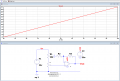
Hi, I am trying to control ops amp output voltage from 0 to 24 volt. Intent to use a digital Pot for VR1. Being a newbie at this like some advise.
what op amp to use to control 24V and if this schematic needs more attention.View attachment 244840
Looking at 40mThat configuration will not allow an output voltage less then the 24V to to the plus input, it can only amplify the voltage.
One way to adjust the output from 0V to 24V is to tie the op amp output directly to the minus input to make it a follower, and then use the pot wiper to output 0V to 24V at the plus input.
How much op amp output current do you need?
If I understand correctly is this what I should be doingWhy not use the Op Amp as a buffer and vary the + input voltage through a pot?
crutschow said the same
But I am controlling this with a digital Pot which does not have 24V toleranceIf I understand correctly is this what I should be doing
View attachment 244847
Sorry for my ignorance. I understand to change from 24 to 6 volt. I did not understand the rest . If I am correct the feedback circuit remains the same.Connect the pot to 6V source and use an opamp with gain of 4.
As the "track" of your digital pot has a resistance of 10K if you connect one end of the track to ground and the other end of the track to +24 volts via a 30K resistor you will have 6 volts across the ends of the track. (You have creates a simple potential divider.)
You then need to configure the OP amp to multiply it's 0 to +6 volt input by 4 to create a 0 to +24 volts output.
Depending on the op amp you use you may need its negative supply pin to be a few volts negative of ground.
Note I have never used digital pots so I am assuming they behave like a normal pot except fot the voltage limitations.
Les.
Noted Thanks Ehi,
Les states 30k.
E
Can I confirm as 100 and 10 ohms for gain of 1.1Thanks
Hi Dave,Can I confirm as 100 and 10 ohms for gain of 1.1