Facebook
 Google
 GitHub
 Linkedin
Well, that changes things. Tang Yew.
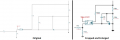
The schematic is hard do read, but that little bit of info is directional. Now I'm wondering if the original schematic is for a stepped-sine-wave type inverter rather than a high-frequency switcher. If so, then wouldn't a plain old 50-60 Hz power transformer hooked up "backwards" work. I've done that at a 10 W scale with an old Radio-Shack part.
OTOH - the schematic in post #1 is mostly a lift of the circuits in the UCC3808 datasheet. That implies a high-frequency switcher with a fixed output voltage.
The datasheet circuit is for 200 kHz. Based on that, this schematic is for around 360 kHz. And, the output is strange. Even though the secondary-side feedback circuit is standard for a DC-output supply, the output has very little filter capacitance and a strange extra pair of diodes. Hmmm ...
TS: What is it you are trying to design? What is the input? What are the output voltage (DC, RMS, etc.), max. load current, and intended load?
ak
Last edited: