V+ in a 5A constant current circuit

Thread Starter

Hattrick23

Joined May 16, 2018
1
Hello,

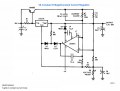
I am trying to implement the attached 5A constant current/voltage regulator for a project. The circuit was found in National's LM317 data sheet, but am a bit confused about it, and was wondering if anyone could help me understand what the circuit is doing.

Mainly two things:
  1. What voltage should be attached to the V+ rail of the op-amp (pin 7)? I've seen people online say both +6v or Vin, but +6v seems to limit the output voltage of the circuit, and Vin doesn't light the LED (which i'm assuming indicates it's not active?)
  2. What is the purpose of the LED? I'm assuming it's meant to indicate that current is being regulated (kept constant), could someone confirm this?
Any advice is greatly appreciated! Thanks! (also sorry if this is the wrong forum to post this on, i'm new to AAC)
 

Attachments

wayneh

Joined Sep 9, 2010
18,104
I haven't read the data sheet in detail for the op amp but it's usually a very bad thing to apply an input voltage to an op-amp that exceeds the power rail voltage. Since the op-amp sees the full output voltage up to 30V on it's non-inverting input, my first pass assumption is that it needs to be supplied the full input voltage of up to 35V. The op-amp can tolerate 44V of supply voltage, so having the negative rail at -6V gives you 41V, which is safely in range.
 

AnalogKid

Joined Aug 1, 2013
12,126
V+ goes to the +35 V input. The chip is rated for 44 V operation, and the span from +35 to -6 is 41 V. Note that many National Semiconductor app circuits (that we all were raised on) never were built or tested by anyone at NS, so this circuit might have problems in the real world. For example. the sch does not show any decoupling capacitors on either opamp power pin. Without them, this circuit will oscillate and make an excellent AM radio jammer.

The LED is a convenient way for the current control loop to be switched into and out of the voltage control loop and indicate which loop is in control at any moment.

Note that the +35 V input is the positive peak value of the ripple on the power supply bulk filter capacitor, not the average value that will be shown on most digital meters.

ak
 

RichardO

Joined May 4, 2013
2,270
Note that many National Semiconductor app circuits (that we all were raised on) never were built or tested by anyone at NS, so this circuit might have problems in the real world.

ak
An engineer where I worked had a PCB made based on a NS app note -- without prototyping it. It was missing an entire inverting stage needed for it to operate properly. :eek:

(This was a long time ago when the PCB layout was a hand-taped artwork).
 

danadak

Joined Mar 10, 2018
4,057
Note that many National Semiconductor app circuits (that we all were raised on) never were built or tested by anyone at NS
I had good fortune of working there in 70's and sitting next to linear applications
and design group. I can say without prejudice (well some prejudice, ok more...)
that many, not all, app notes these circuits were indeed built. Clearly cut and pastes
were order of the day showing one more billionth inverting amplifier schematic, but
on the more involved circuits many of them were built. One only has to look at Bob
Pease's office photos to see an aircraft carrier sized pile of prototypes.

This was true of the Hybrid group as well who I often had lunch with their manager
and my groups manager.

Regards, Dana.
 

RichardO

Joined May 4, 2013
2,270
An engineer where I worked had a PCB made based on a NS app note -- without prototyping it. It was missing an entire inverting stage needed for it to operate properly. :eek:
I can say without prejudice (well some prejudice, ok more...)
that many, not all, app notes these circuits were indeed built. One only has to look at Bob
Pease's office photos to see an aircraft carrier sized pile of prototypes.

Regards, Dana.
In all fairness, I should have noted that the problem with the circuit in the application note was probably a transcription error that was introduced by the draftsman.

Bob Pease prototype: (Note the props elevating the test equipment).
upload_2018-5-17_11-3-37.jpeg


The Jim Williams prototypes for his app. notes were equally impressive:
upload_2018-5-17_10-59-22.jpeg
 
Top