Using polarized capacitors when they are not on the drawing

Thread Starter

Nick De Baerdemaeker

Joined Jun 18, 2018
22
Hello.

first of all the question:
Can I use polarized capacitors in a location where they shouldn't be polarized? And if so, does it matter how they are connected ?

I've been in the process of restoring a jukebox. Recently I figured out that the junction box, which holds quite a bit of resistors fuses and capacitors, has three large capacitors from the 60-ies... Needless to say they have to be replaced with more recent ones.
They are:
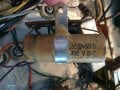
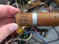
50 WVDC 100 MFD wurlitzer part no. 73862
100mfd.JPG
50 VDC 500 MFD wurlitzer part no. 71816
500 mfd.JPG
400 VDC 0.5 MFD wurlitzer part no. 73099-140
400v.JPG

This however has prooven to be quite the challenge.

I have bought the replacement capacitors which are on their way, however I overlooked an important bit...
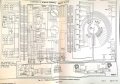
According to the schematic drawing (see attachment) only one capacitor has to be polarized, the other two simply have the icon for capacitor with their respective values.

Those two capacitors that are currently inside the jukebox are polarized, and I bought the replacements based upon their values.

Any thoughts are welcome :)
MOD: lightened up your circuit image.
 

Attachments

Last edited by a moderator:

Dodgydave

Joined Jun 22, 2012
11,303
I would say the 0.5Mfd 400v (73099)and the 500Mfd 50v (71816)are Non Polarised, as the are across coils/solenoids used for back emf suppresion.
 

ScottWang

Joined Aug 23, 2012
7,400
Using a polarized capacitors to replacing an non-polarized capacitors, some circuits are ok, but they still depend on the circuits and should be case by case, when you doing this then you should be care which side that the voltage is more higher and put the (+) pin on that side.

Or you can in series with two polarized capacitors and connected two (+) pins together or two (-) pins together, but the values of capacitance will be divided by 2.
 

AlbertHall

Joined Jun 4, 2014
12,346
If the capacitors have a DC voltage across them then you can use a polarised replacement.
In days of old a 500uF capacitor would have been polarised.
 

Thread Starter

Nick De Baerdemaeker

Joined Jun 18, 2018
22
I have uploaded three photos of the actual caps that are currently in place. I assumed they all were polarized.
They appear to all be D.C.
  1. The 50 WVDC 100 MFD (paper), also has plus signs next to the word AMCON,
  2. The 50 VDC 500 MFD (yellow), carries plus signs, and a ribbon,
  3. The 400 VDC 0.5mfd (wax) has a ribbon, I assumed this is negative.
 

Attachments

Dodgydave

Joined Jun 22, 2012
11,303
Unless they have a + / - sign on them i would say Non Polarised, it won't make a difference if you put non Polarised instead of Polarised ones. All capacitors are rated in DC.
 

ScottWang

Joined Aug 23, 2012
7,400
I have uploaded three photos of the actual caps that are currently in place. I assumed they all were polarized.
They appear to all be D.C.
Yes, I also thought about that.

* The 50 WVDC 100 MFD (paper) -- I can't identify which pin is (+) from the picture.

* The 50 VDC 500 MFD (yellow) -- The right side has labeled "+", so it is Positive.

* The 400 VDC 0.5mfd (wax) has a ribbon, I assumed this is negative -- Normally I will also treat it as Negative.
 

Thread Starter

Nick De Baerdemaeker

Joined Jun 18, 2018
22
Thanks so far.
For the 500 MFD 50 VDC I can't seem to find a non polarized version on the mouser page.
(non polarized judging from the electrical schematic)
Since they're not on the mouser site they are probably rare, also likely the reason why there is a polarized version inside the junction box at the moment.

I dont think I can go wrong here by replacing it with an axial cap that has the same values and connect it the way it sits right now.

https://www.mouser.com/Passive-Components/Capacitors/_/N-5g7r?P=1yx4avvZ1z0wqss


Just out of curiousity, the wax 500MFD 50 VDC is what they call an axial electrolyt cap, correct me if I'm wrong.
Does it have to be an electrolytical cap to replace it or not, is there any difference in the way that they operate as opposed to say film caps ?
 
Last edited:

AlbertHall

Joined Jun 4, 2014
12,346
Just out of curiousity, the wax 500MFD 50 VDC is what they call an axial electrolyt cap, correct me if I'm wrong.
Does it have to be an electrolytical cap to replace it or not, is there any difference in the way that they operate as opposed to say film caps ?
Electrolytic capacitors generate an insulating layer (typically aluminium oxide) on one of the metal films by electrolytic action. That layer acts as the dielectric in the capacitor and is why polarity matters. If the polarity is reversed electrolytic action begins to remove the existing oxide layer and build the oxide layer on the other electrode. While this is happening there is no effective insulation and there will be lots of leakage current.

'Film' capacitors use an insulating sheet between the two metal electrodes. That film nowadays will be a plastic of some sort - polypropylene, polyester, etc. In days gone by this might have been waxed paper.

Both types of capacitor work in essentially the same way though they have slightly different detail properties which may be significant in critical circuits - leakage current, series inductance and resistance, maximum ripple current, tolerance, temperature dependance...
 

ScottWang

Joined Aug 23, 2012
7,400
I believe this is a paper capacitor and the band marks the outer foil connection.
The capacitors and the small carrier bring my memories back to over 40 years ago, and that was the tubes age in my school time, we just learned the theories of Tubes Radio. one day, I was disassembly all components from the bad Tubes Audio to checked which one was damaged, and my daddy blamed me why I destroyed the Radio, because the Radio was his baby, and it was also accompany with me in my childhood, sometimes I was disassembly the capacitors, and they were rolled with some papers including the Aluminum foils.
 

Thread Starter

Nick De Baerdemaeker

Joined Jun 18, 2018
22
Opening this junction box has revealed more problems than I could foresee.

I thought that one end of the cap got "stumped" with plastic. Upon further examination it seems that this once was a 10 ohm resistor.
This has sat there broken from the very start so all the issues that I had with the jukebox are finally starting to make sense...

according to the manual it's a 10 ohms half watt resistor.
Thoughts to a correct replacement would also be appreciated. (some photos below)

Also today the first replacement caps came in, I've lined them up with the ones still in place and how I would replace them.
However, the broken resistor sits with a cap that, according to the diagram, should be non polarised... could this have been the reason why they broke it ?

thanks for your help so far all, it's been really REALLY enlightning !!!

IMG_3705.JPGIMG_3702.JPGIMG_3708.JPGIMG_3706.JPGIMG_3707.JPG
 

ScottWang

Joined Aug 23, 2012
7,400
However, the broken resistor sits with a cap that, according to the diagram, should be non polarised... could this have been the reason why they broke it ?
The thing could be like this -- The values of watts was not enough when the big current flows through it, day by day, and then the resistor unable to withstand the heat any more, so it was broken.

Maybe you can choose a resistor with 2 ~ 5 watts.
 

Ylli

Joined Nov 13, 2015
1,087
If the 500 uF cap was leaky, that could have increased the dissipation of the 10 ohm resistor. Just replace it along with the caps. Maybe use a 1 watt. BTW I agree with your polarity on the 100 uF and 500 uF caps. The 0.5 uF original is nonpolarized and a nonpolar replacement might be best.
 
Top